
Jeremy_Sawatzky
Well-known member
Hi everyone i recently started my camera crane build. I had no design or plan drawn up whatsoever. I was literally sitting at the computer, thought to myself id like to have one of those and walked out the door. I drove to the metal shop.
Since i cant see a project in my head without seeing available materials, i stayed there about 2 hours drawing on paper, going over what i would need all thought up on the spot in my head. (needless to say im good friends with the metal shop guys now
after a purchase of about 110 bucks in aluminum i came home with the most crucial pieces needed to start my build. I also picked up a couple boxes of 1/4in bolts and nuts along with an assortment of larger bolts, washers, nuts and bearing assembly.
My available tools at home consisted of a drill press, table saw and ratchet set so on. No band saw
I decided on aluminum for the build due to its inherent lightness. Steel would have been nice to weld but much harder to cut, drill and so on. Not to mention the finished product would have probably weighed 100lbs. Aluminum is nice and soft, quiet and not so hard on the tools
I didnt really think at the start of the build to properly document how i built it but the pictures i have are pretty self explanatory.
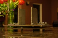
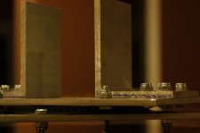
I started out by building this: 2 plates 9in by 7in sandwiched together with a bearing assembly, and the start of a tower mounted on top. as u ca see im going to be using alot of bolts and nuts for this project.


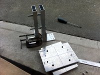
then i built the tower that would hold the 2 arms and incorporated it onto my base, note the larger bolts that the arms will be attached with.

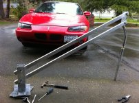
Then i took my 2 5 foot aluminum arms, drilled them to fit the bolts and made a coupling piece for the end. wow a camera crane lol - oh but im no where near done

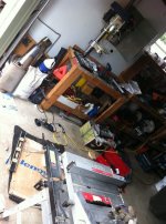
my workshop

I had decided from the beginning i wanted about 9 feet of arm on the boom but at the same time be able to carry the rig around in a small car. So i set myself a maximum length of 6 feet.
The arms would consist of 2 5 foot pieces that could extend or retract to your desired length. Or you could remove the secondary set of arms entirely and just use 2 5 foot pieces.
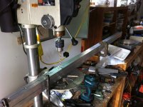
So i set about drilling holes in both arms 3in apart
note: when working with aluminum do yourself a favor and buy a set of nice drill bits. Dont bother that $7 set on sale. Spend at least $35 on a set of titanium or $75 on a set of cobalt drill bits. They will will not warp or lose their sharpness.

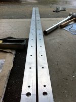
because i drilled both pieces at once i know they are identical

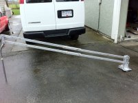
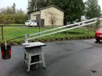
add the secondary set of arms and 4 pins to hold it together and ive got my retractable 9 foot reach :thumbsup:


I couldnt help but toy with it - lots more work to come!

Next i needed to replace that table saw with a proper tripod. And something very solid. I chose not to incorporate a pre-built tripod as my base because with the amount of weight was putting on it, the legs of most tripods would flex and bend, not to mention ruin the head.
This is a good place to mention from here on was more trips to the metal shop and lots of trips to hardware stores for bearings, bolts and so on. About another $150 bucks
So i started with a simple plate - and lots of measuring - the 4 holes are for the 4 bolts that extend out the bottom on the base of the crane. need something to sit on!

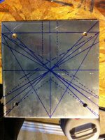
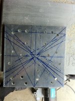
Dont worry - these holes arent randomly placed :huh:

These angle plates extend 3 in downwards - it will make sense dont worry

Lots of those nuts and bolts

Then the 3 tripod legs get sandwitched between the plates with bolts.


The crane sits on the plate (there is now a holding pin so the 2 cant come apart accidentally)


Obviously the legs needed some holders so they dont go flying outwards

Its astonishing how solid the tripod is, Not 1mm of give in any direction.
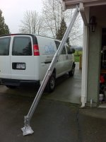
I chose not to make the legs extendable (for now) because the crane itself does that and going any further down will reduce how high the crane can go (due to counter weights hitting ground) and going higher would make it hard to operate

Long list of things still to do. In this pic you can also see the new weight system being built

Guess what comes next?

Yep a full 360 remote head - Now it gets tricky
note: i had the controller and receiver assembly from a rc car. But it needed some extra parts to make it work for my application, different battery, speed control, gears and so on. about $90
Starting to build the horizontal axis assembly

cheesplate

Because you have to make the whole rig balanced, you need to be able to adjust the cameras center of gravity - vertical adjustment


Next is the Rotation assembly. All of the motors, battery, reciever, speed control will be mounted on the moving assembly. therefore there needs to be a fixed gear for the low rpm high torque motor to spin itself around

Where the camera will sit approximately

And thats how far ive gotten on the build. Lots to do still, im waiting on a couple parts to be machined and for the specialty low rpm motor to arrive.
here is a couple videos i took with my iphone mid build
http://www.youtube.com/watch?v=A0SQnDFInSg&feature=related
http://www.youtube.com/watch?v=q0-gRus9k50
Il be updating!
Since i cant see a project in my head without seeing available materials, i stayed there about 2 hours drawing on paper, going over what i would need all thought up on the spot in my head. (needless to say im good friends with the metal shop guys now
after a purchase of about 110 bucks in aluminum i came home with the most crucial pieces needed to start my build. I also picked up a couple boxes of 1/4in bolts and nuts along with an assortment of larger bolts, washers, nuts and bearing assembly.
My available tools at home consisted of a drill press, table saw and ratchet set so on. No band saw
I decided on aluminum for the build due to its inherent lightness. Steel would have been nice to weld but much harder to cut, drill and so on. Not to mention the finished product would have probably weighed 100lbs. Aluminum is nice and soft, quiet and not so hard on the tools
I didnt really think at the start of the build to properly document how i built it but the pictures i have are pretty self explanatory.
I started out by building this: 2 plates 9in by 7in sandwiched together with a bearing assembly, and the start of a tower mounted on top. as u ca see im going to be using alot of bolts and nuts for this project.
then i built the tower that would hold the 2 arms and incorporated it onto my base, note the larger bolts that the arms will be attached with.
Then i took my 2 5 foot aluminum arms, drilled them to fit the bolts and made a coupling piece for the end. wow a camera crane lol - oh but im no where near done
my workshop
I had decided from the beginning i wanted about 9 feet of arm on the boom but at the same time be able to carry the rig around in a small car. So i set myself a maximum length of 6 feet.
The arms would consist of 2 5 foot pieces that could extend or retract to your desired length. Or you could remove the secondary set of arms entirely and just use 2 5 foot pieces.
So i set about drilling holes in both arms 3in apart
note: when working with aluminum do yourself a favor and buy a set of nice drill bits. Dont bother that $7 set on sale. Spend at least $35 on a set of titanium or $75 on a set of cobalt drill bits. They will will not warp or lose their sharpness.
because i drilled both pieces at once i know they are identical
add the secondary set of arms and 4 pins to hold it together and ive got my retractable 9 foot reach :thumbsup:
I couldnt help but toy with it - lots more work to come!
Next i needed to replace that table saw with a proper tripod. And something very solid. I chose not to incorporate a pre-built tripod as my base because with the amount of weight was putting on it, the legs of most tripods would flex and bend, not to mention ruin the head.
This is a good place to mention from here on was more trips to the metal shop and lots of trips to hardware stores for bearings, bolts and so on. About another $150 bucks
So i started with a simple plate - and lots of measuring - the 4 holes are for the 4 bolts that extend out the bottom on the base of the crane. need something to sit on!
Dont worry - these holes arent randomly placed :huh:
These angle plates extend 3 in downwards - it will make sense dont worry
Lots of those nuts and bolts
Then the 3 tripod legs get sandwitched between the plates with bolts.
The crane sits on the plate (there is now a holding pin so the 2 cant come apart accidentally)
Obviously the legs needed some holders so they dont go flying outwards
Its astonishing how solid the tripod is, Not 1mm of give in any direction.
I chose not to make the legs extendable (for now) because the crane itself does that and going any further down will reduce how high the crane can go (due to counter weights hitting ground) and going higher would make it hard to operate
Long list of things still to do. In this pic you can also see the new weight system being built
Guess what comes next?
Yep a full 360 remote head - Now it gets tricky
note: i had the controller and receiver assembly from a rc car. But it needed some extra parts to make it work for my application, different battery, speed control, gears and so on. about $90
Starting to build the horizontal axis assembly
cheesplate
Because you have to make the whole rig balanced, you need to be able to adjust the cameras center of gravity - vertical adjustment
Next is the Rotation assembly. All of the motors, battery, reciever, speed control will be mounted on the moving assembly. therefore there needs to be a fixed gear for the low rpm high torque motor to spin itself around
Where the camera will sit approximately
And thats how far ive gotten on the build. Lots to do still, im waiting on a couple parts to be machined and for the specialty low rpm motor to arrive.
here is a couple videos i took with my iphone mid build
http://www.youtube.com/watch?v=A0SQnDFInSg&feature=related
http://www.youtube.com/watch?v=q0-gRus9k50
Il be updating!
Attachments
-
 208461_10150555272370455_563420454_18146878_2417899_n.jpg43.6 KB · Views: 0
 -
 221972_10150555272430455_563420454_18146880_7181737_n.jpg35.1 KB · Views: 0
 -
 222997_10150557947085455_563420454_18184738_2836110_n.jpg106.5 KB · Views: 0
 -
 217517_10150557947350455_563420454_18184744_7110259_n.jpg113.3 KB · Views: 0
 -
 215265_10150557947675455_563420454_18184752_5468483_n.jpg97 KB · Views: 0
 -
 224037_10150557948320455_563420454_18184763_8018756_n.jpg90.7 KB · Views: 0
 -
 225141_10150557949140455_563420454_18184783_2251965_n.jpg82.5 KB · Views: 0
 -
 217997_10150557950190455_563420454_18184806_5585424_n.jpg87.1 KB · Views: 0
 -
 215665_10150557951185455_563420454_18184823_785426_n.jpg109.1 KB · Views: 0
 -
 225097_10150557952180455_563420454_18184837_336160_n.jpg119.4 KB · Views: 0
 -
 215401_10150562676870455_563420454_18252552_7070881_n.jpg104.3 KB · Views: 0
 -
 225320_10150562677225455_563420454_18252559_4469476_n.jpg107.8 KB · Views: 0


