GH1 Stereoscopic Rig Collaboration

Should we switch to the forum proposed by Vitaliy?

Might be easier to communicate in depth there. It would be good to have a basic sticky guide to building and testing a simple controller, for those new to the topic (so they don't have to sort thru 34 pages of posts). Also, there are some testing parameters that would be useful to keep sticky as well. Finally, it would be nice to have a place to put links to footage and a sticky guide to 3D players (e.g. stereoscopic player). We could easily make this much more accessible for newcomers.

It would not, however, be much fun to have to duplicate that effort in two locations - so - we need to make the switch totally or not at all, in my opinion.
 
...it is about 0.7ms and it reaches 0ms in 1 minute and 0.7ms in the opposite direction

Crunchy, how close are your two GH1s in serial number and/or manufacturer date? I continue to wonder how much manufacturing lots matter in GH1 drift characteristics. Both of my GH1s and my GH2s are sequential serial numbers, so that is all I have tested.
 
It would be good to have a basic sticky guide to building and testing a simple controller, for those new to the topic (so they don't have to sort thru 34 pages of posts). Also, there are some testing parameters that would be useful to keep sticky as well. Finally, it would be nice to have a place to put links to footage and a sticky guide to 3D players (e.g. stereoscopic player). We could easily make this much more accessible for newcomers.

It would not, however, be much fun to have to duplicate that effort in two locations - so - we need to make the switch totally or not at all, in my opinion.

Good ideas! I Agree.
 
Crunchy, how close are your two GH1s in serial number and/or manufacturer date?

Mine are quite far apart from each other (more than 6 months). The highest chance to have small drift is to buy cameras with consecutive serial numbers. However, even then you can't be sure (depends on crystal characteristics). I don't believe that they changed electronic circuits.
 
Crunchy:

This isn't a 3D question specifically, but, what video settings did you use for the 2 samples that you posted? Your video is exceptionally clear and sharp!

-- David
 
... but, what video settings did you use for the 2 samples that you posted? Your video is exceptionally clear and sharp!

Are you sure? Your "elephant clip" was very sharp.
I am using FHD mode, 25p (in 50i wrapper), and lpowell 75Mbps patch. I think that I used lower bitrate for some of the clips in parallel configuration (about 40Mbps). I used STANDARD mode with all settings = 0 except Noise reduction: NR=-2. Lenses were Panasonic 14-42mm F3.5-5.6.

There are some more interesting clips, so I'll try to upload them as soon as I get some more time (now I'll continue with developing firmware for "3DSLR Master").

I also found out that the clips with beam-splitter are having very similar colours if manual white balance (MWB) is applied before shooting. I have even used the same MWB setting the next day and the colours were still very similar.
 
Might be easier to communicate in depth there.

I agree, it's easier to upload pictures and videos for one. I think Vitaliy's pages would be best for firmware hack related ideas and goals.

It would be good to have a basic sticky guide to building and testing a simple controller, for those new to the topic (so they don't have to sort thru 34 pages of posts). Also, there are some testing parameters that would be useful to keep sticky as well. Finally, it would be nice to have a place to put links to footage and a sticky guide to 3D players (e.g. stereoscopic player). We could easily make this much more accessible for newcomers.
Good idea, unfortunately my time is too short to help a lot. How about we just use the 1st post in this thread to keep up-to-date info, and links to the many useful posts in this thread? My posts on powering and monitoring would be useful, as well as our various rigs, test videos, definitely the tests done so far and what more needs to be done.
 
Last edited:
No cross-conduction? But the cameras have already the common ground, since you usually need it for sending remote signals (by means of micro-controller)?!? So if one camera is switched on, the other will be switched on as well.

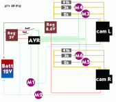
Here's a simplified overview of my proposed circuit (easer to explain). The 'M's are enhanced N-channel MOSFETS, so the idea is to switch between load & ground. See any problems?

GH23D-Circuit.gif
pencil.png
 
Speaking of monitoring, how are you guys monitoring in stereo? I'm just in talks with LCD controller manufacturers. Turns out there are some other interesting panels out there, including a 4.8" 1024x600 one.
 
Here's a simplified overview of my proposed circuit (easer to explain). The 'M's are enhanced N-channel MOSFETS, so the idea is to switch between load & ground. See any problems?

As far as I can see, you depicted only remote control for the left camera (including switches M3 and M4). Similar circuit holds for the right one. However, in order to control them with the same AVR you must have a common ground. So, minus sign for remote control on the left camera and minus sign for the remote control of the right camera (which is not shown) are in fact connected. Therefore, you have ALREADY connected both ground signals. Therefore you cannot switch on independently left and right cameras.
 
As far as I can see, you depicted only remote control for the left camera (including switches M3 and M4). Similar circuit holds for the right one.

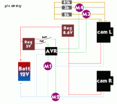
Right, I didn't show the (duplicated) circuit for the right camera just to keep the diagram clean. Updated version below.

However, in order to control them with the same AVR you must have a common ground. So, minus sign for remote control on the left camera and minus sign for the remote control of the right camera (which is not shown) are in fact connected.
Hmm - AFAIKS the remote grounds aren't connected directly, as they both return to their respective cameras. Of course both cameras are ultimately connected to the same ground via their power lines, but that's not what you mean right?

Maybe I'm misunderstanding the N-channel MOSFETS. Considering their Source/Drain/Gate, I think of the Source->Drain (and therefore the remote +>-) as a separate circuit, which the Gate input controls by +ve voltage. Is that wrong?
 

Attachments

  • GH23D-Circuit2.gif
    GH23D-Circuit2.gif
    20.9 KB · Views: 0
Last edited:
As can be seen from the scheme, AVR has the same ground as 12V battery's ground. So AVR out signals (which control different switches) are somewhere between 0V and 5V according to 0V from the battery. Now, if the cameras are not switched on, the negative voltage on the cameras will be approx. at the same potential as 8.6V regulator. So, camera's ground signal will be at approx. 8.6V and AVR output voltage at 0-5V. This won't work. The only way to do it is to use opto-couplers with switches M3 to M6. Are you going to measure missynch from video composite signal as well?
 
I have just checked my transistors. I'm using FDD 4685 P-type MOSFET and am switching the positive lines. Of course, you'll need simple transistor inverter in between to switch on/off the MOSFET.
On the other hand, I am always exaggerating with the components, so you don't need so strong MOSFET to switch on the power.

My advice: your life will be much easier if you switch on positive lines instead of negative. :)
 
As can be seen from the scheme, AVR has the same ground as 12V battery's ground. So AVR out signals (which control different switches) are somewhere between 0V and 5V according to 0V from the battery.

Yep.

Now, if the cameras are not switched on
Do you mean 'switched on' at the MOSFETS M1/M2, or on their dial? I intend to keep the dials on permanently.

, the negative voltage on the cameras will be approx. at the same potential as 8.6V regulator.
This is the bit I'm unsure about (lack of experience). Let's assume you're right...

So, camera's ground signal will be at approx. 8.6V and AVR output voltage at 0-5V. This won't work.
... do you mean because the Gate voltage has to be >= Source V + 3.3V (for a cmos logic-level mosfet)?

The only way to do it is to use opto-couplers with switches M3 to M6.
Why does it affect my remote switches? I'm not switching the remote signal when the cameras are off. When the camera's on, the remote line is at 2.45V.

If I switched the camera power lines with a P-channels, could I keep the N-channels for the remote lines as-is?

Are you going to measure missynch from video composite signal as well?
Not in the first version. If sync is very reliable in CRT tests & in practice, I won't bother.
 
...In most cases they are in synch, but sometimes it happens that they differ.

I tested with Panasonic 14-42mm lenses, using the AF half-push trick. Out of 20 test runs, I had 5 with blown sync (>35ms !!). The remaining 15 runs had an average initial sync of .12ms. This is very similar to my first tests with M4/3 lenses... a percentage of totally blown syncs and the remainder were pretty good. Also, VSYNC isn't a reliable indicator for me of blown sync... I have a run, for example, where the VSYNC was .01 ms and the CRT sync tester sync was 4.72ms.

For comparison, my average initial sync with manual lenses is .085ms.

How are you rejecting the cases of mis-sync with your rig, Crunchy? With VSYNC? I guess you are right that PAL VSYNC may be a more reliable indicator of actual integrator clock than NTSC.
 
Not sure if I'm allowed to post such info here or not - so, I'll delete this post if necessary.

I'm selling my trusty 3D Film Factory Indie Beamsplitter rig on ebay (http://cgi.ebay.com/ws/eBayISAPI.dl...62068&ssPageName=STRK:MESELX:IT#ht_500wt_1156). Here's a link to the 3DFF product site - http://www.3dfilmfactory.com/index....bs-indie-rig-beam-splitter&catid=44&Itemid=76

While I LOVE this rig, and it's been the bomb for testing different cameras, it has some pros and cons. The pros are that it's ROCK steady and perfectly square (the 3D geometry that it produces is fantastic). It also has a huge mirror (10 X 17") that permits a large inter-axial with very wide-angle lenses. It's perfect for GH1s and GH2s - right out of the box. If a GH1/2 user winds up buying it, I'll even throw in some rock-solid quick-release and slide adjusters that make configuration on the fly even easier.

The cons are that it's BIG, bulky and overbuilt. Probably overkill for the GH1. More appropriate for a RED, EX3, XF-305. The size and build makes it harder to pack for travel and clumsier to move around than is necessary for a DSLR rig. I've been testing a prototype of a new rig (more to come) that is really ideal for DSLR setups, size and weight wise - but - it will be substantially (3X-ish) more expensive.

That all said - someone is going to get a heck of a deal on a great rig for shooting 3D. It would be cool if it's a GH'er!
 
Last edited:
Do you mean 'switched on' at the MOSFETS M1/M2, or on their dial? I intend to keep the dials on permanently.

This is the bit I'm unsure about (lack of experience). Let's assume you're right... ... do you mean because the Gate voltage has to be >= Source V + 3.3V (for a cmos logic-level mosfet)?

Yes. When the cameras are switched off (during power off/on procedure and when you don't want to spend too much current from the batteries) the minus power will be close to 8.6V potential. There will be too large voltages between your controller and the camera.

Why does it affect my remote switches? I'm not switching the remote signal when the cameras are off. When the camera's on, the remote line is at 2.45V.
If I switched the camera power lines with a P-channels, could I keep the N-channels for the remote lines as-is?

Even when they are off there might be some current running from remote input to plus power of the cameras. This might be problematic and it is better to avoid it if possible.
I think that you can keep N-channels for remote (if you'll have common ground).

Not in the first version. If sync is very reliable in CRT tests & in practice, I won't bother.
Again this is very good news. So, if you are sure that the missynch is always close to zero or at most whole number of frames, then it's it. You don't need composite signal. However, check synch time to time (e.g. by using a CRT screen or by using higher shutter speeds and taping yourself when rapidly moving your hand up and down).
 
I tested with Panasonic 14-42mm lenses, using the AF half-push trick. Out of 20 test runs, I had 5 with blown sync (>35ms !!). The remaining 15 runs had an average initial sync of .12ms. This is very similar to my first tests with M4/3 lenses... a percentage of totally blown syncs and the remainder were pretty good. Also, VSYNC isn't a reliable indicator for me of blown sync... I have a run, for example, where the VSYNC was .01 ms and the CRT sync tester sync was 4.72ms.

How are you rejecting the cases of mis-sync with your rig, Crunchy? With VSYNC? I guess you are right that PAL VSYNC may be a more reliable indicator of actual integrator clock than NTSC.

I have a little better results concerning synch. Maybe it's due to micro-controller based control which takes care about exact timing. However, my findings show that Video synch and the actual synch are totally correlated.
What do I do when I see that the shots are not in synch when starting shooting? I simply stop shooting immediately. Afterwards it's not a problem to delete very very short files on a PC before editing.
 
Last few days I was very busy in adding some features to the 3DSLRM (e.g. time-lapse). Finally, I can say that it's now much more useful than before (you can set some of parameters by 4-way switch). The battery voltage is shown as well and "focus" and "shooting" states are also displayed. There is also a menu system.

One very short time-lapse (in parallel format) made by 3DSLRM is here:
http://www.sendspace.com/file/1duvqr
 
I...my findings show that Video synch and the actual synch are totally correlated.

Have you seen this correlation in VSYNC with NTSC, by any chance? This seems to be a key to success with M4/3 lenses... if I had a reliable indication of sync, I'd simply power-cycle and try again (like we do with LANC).

I do think I need to complete my solid-state controller.... if for no other reason than to eliminate the risk of mechanical bounce.
 
Back
Top