
Navigation
Install the app
How to install the app on iOS
Follow along with the video below to see how to install our site as a web app on your home screen.
Note: This feature may not be available in some browsers.
More options
You are using an out of date browser. It may not display this or other websites correctly.
You should upgrade or use an alternative browser.
You should upgrade or use an alternative browser.
F35: Yachacha light weight F35 build thread
- Thread starter SJX
- Start date

EricLBrown
Member
This is really intriguing. Tracking this post for sure!
I need assistant panel and cable. I have lots of interesting F35 items for trade. PM me if anyone has one they don't want.
I am still plugging along, it's waiting for parts that is biggest hold up. I've deserted all the original F35 case parts and decided making my own faceplate is actually simpler. If anyone has a Nikon converted front plate from smallHD it was really brilliant what they came up with and basically I can transfer the parts they made to my new frontplate and it keeps all the distances for the mount where they should be. The speed booster obviously suggests itself when I start looking at the new front, however it doesn't measure out nice, the glass needs to be where the green IR filter is.
I've widdled down the parts I need and the parts I don't to make the F35 work. Basically some of the hardware boards performs a sort of digital handshake, others it doesn't care about. If the fans aren't all plugged in, it will give errors also.
It's a lot of guess and check, that's always been my method but I do have confidence I can complete the task without any major roadblocks.
G
Guest
Guest
I need assistant panel and cable. I have lots of interesting F35 items for trade. PM me if anyone has one they don't want.
I am still plugging along, it's waiting for parts that is biggest hold up. I've deserted all the original F35 case parts and decided making my own faceplate is actually simpler. If anyone has a Nikon converted front plate from smallHD it was really brilliant what they came up with and basically I can transfer the parts they made to my new frontplate and it keeps all the distances for the mount where they should be. The speed booster obviously suggests itself when I start looking at the new front, however it doesn't measure out nice, the glass needs to be where the green IR filter is.
I've widdled down the parts I need and the parts I don't to make the F35 work. Basically some of the hardware boards performs a sort of digital handshake, others it doesn't care about. If the fans aren't all plugged in, it will give errors also.
It's a lot of guess and check, that's always been my method but I do have confidence I can complete the task without any major roadblocks.
I'll DM you

rbirnbaum
Well-known member
I need assistant panel and cable. I have lots of interesting F35 items for trade. PM me if anyone has one they don't want.
I am still plugging along, it's waiting for parts that is biggest hold up. I've deserted all the original F35 case parts and decided making my own faceplate is actually simpler. If anyone has a Nikon converted front plate from smallHD it was really brilliant what they came up with and basically I can transfer the parts they made to my new frontplate and it keeps all the distances for the mount where they should be. The speed booster obviously suggests itself when I start looking at the new front, however it doesn't measure out nice, the glass needs to be where the green IR filter is.
I've widdled down the parts I need and the parts I don't to make the F35 work. Basically some of the hardware boards performs a sort of digital handshake, others it doesn't care about. If the fans aren't all plugged in, it will give errors also.
It's a lot of guess and check, that's always been my method but I do have confidence I can complete the task without any major roadblocks.
Great news! I have a Assistant Panel, if no-one wants to trade, I can send it to you for a few months for this build phase.
Looking forward to new pics when the parts arrive and thanks for sharing your progress.

DarkMatter
Veteran
Great idea! Can’t wait to see this evolve! Following!
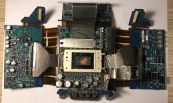
Here is something no one has seen before. The metal and plastic shielding is very important in the F35. I understand why companies don't want to make analog sensors anymore, this thing is so complex.
Very sorry for the delay, day job got busy. I am making progress again and have narrowed down almost all the questions and parts I need. My last questions revolve around the front plate. My F35 has always been Nikon, but the landscape of low cost PL Lens has changed dramatically in the last 4 years and now PL is within reach. But if I go with the speed-booster, which I really want to, then Nikon almost makes more sense to stick with full frame lens options.
Went on a side adventure and bought F35 with smashed ccd. For $700 a complete set of parts is worth it to me. F23 is a good option for spare F35 parts also. I also plopped my F35 NIkon plate with good CCD Into the new F35 body and now I have a working F35 while I am working on this project. I was feeling bummed that the F35 was down and I couldn't film my dog when he is sleeping.
Having a CCD unit I can take apart completely, I am sure of the speed-booster now. Once I can figure out the right way to do a new face plate, the rest of the camera I have parts for now.
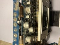
Crazy the impact pushed the ccd down look at bent pins. There are 3 pieces of glass in front of F35 CCD Sensor. This was not done by a lens mishap, almost seems like it was stabbed on purpose. Seller told me it came from computer recycling at CBS Lot.
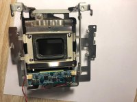
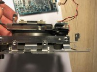
This is the space for the back focus mechanism. Really cool engineering, the whole CCD unit is designed to move forward and back slightly. Possibilities of M43 or E Mount if you were to remove this part, however I feel like it is a great feature of the F35. You basically have the power to slightly move the ccd a few mm's forward or backwards in a very precise manner, which helps a lot if a lens can't reach infinity.
Last edited:
G
Guest
Guest
Thanks!
G
Guest
Guest
Have you considered Minolta glass? Limited on zoom gllas but the ficrotation is the same as most cinema lenses and the look is something closer to what is cinematic imho

Run&Gun
Veteran
It's always amazed me when we've had to crack open older Sony cameras and just how they looked inside. Like they were designed by the military. The F900 inside looked like it was designed by the army or NASA. These "older" cameras, like our ENG cameras were designed to function under extreme conditions.
Sony also put a "back focus/flange depth" adjustment in the F55/F5. To my knowledge, no other camera since has had it. I know the Venice doesn't.
Sony also put a "back focus/flange depth" adjustment in the F55/F5. To my knowledge, no other camera since has had it. I know the Venice doesn't.
G
Guest
Guest
It's always amazed me when we've had to crack open older Sony cameras and just how they looked inside. Like they were designed by the military. The F900 inside looked like it was designed by the army or NASA. These "older" cameras, like our ENG cameras were designed to function under extreme conditions.
Sony also put a "back focus/flange depth" adjustment in the F55/F5. To my knowledge, no other camera since has had it. I know the Venice doesn't.
Like the scene in 2001: a space odyssey when the guy tries to pull out operating panels of HAL

Matt Gottshalk
Resident Preditor
Daisy.....daisy....
Ok I know this is hard to imagine from these photos but I am actually making a lot of progress now. I Still need to sand/cut more but I am using the original Sony skeleton as starting point. It is really hard to build a model without directions but as I get closer to seeing what fits where, I have the confidence to start modifying the original parts.
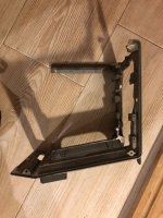
Having the 2nd F35 has made it a lot easier to work. I have one completely taken apart and one still put together. I am really kicking myself for selling the extra ccd block I had a few years ago. I also can breath easier knowing I have 2 of everything.
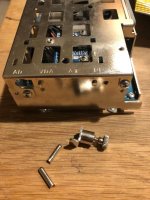
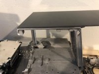
The Fat side of the F35 contains basically the motherboard and powerful image processing chips. It needs to be as big as it is because the boards are squares. Sony designed a very good "Box" for these parts. It is cooled by holding the boards like a sandwich with space in between and 2 fans vent air from the back of the camera and exhaust out the front. If I try to make this fit into a new box, I end up with empty corners, the rounded Sony case is form fitted. So by keeping this side, I can keep all the mounting points for the F35 boards, and Sony has already made a perfectly fitting case for the parts. You see the tab on the bottom of the square board, this board basically dictates the top and bottom extremes of how short you can make the F35.
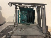
The problem is the rest of the camera. Look at the side of F35 with side off. Loose the memory stick reader. The other side is only the ethernet/12v/24v/remote connectors. The GD power supply (as I have come to call it) is the reason for the 1.5 inches at the bottom of the F35. Without this down there, the entire bottom level of the camera can be raised up to the expansion boards. The CCD can slide up a tiny bit also (not much very dangerous to stress these cables).
Don't think the power supply can be shrunk. Parts of the camera need 65v so and the shielding from the rest of the camera and the CCD unit is important. I don't want to mess with removing the metal cage around power supply and am going to keep original cooling fan.
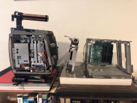
The power supply is going to fit Vertical, basically inside the section that the rear dock used to fill. I need to saw off the PCB sticking out the top where the LEMO Connector is attached. Nervous but it is necessary.
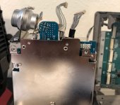
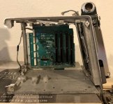
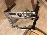
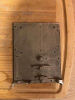
I am improving cooling to the CCD by having this fan suck air from a vent under the top handle. I going to keep the original baseplate, it is very light weight. The power supply will fit once I Dremel out the inside of the back dock enough.
I can make the GD IF Box all fit inside also. The IF Box boards are limited by cable length which makes placement a riddle to figure out.
Having the 2nd F35 has made it a lot easier to work. I have one completely taken apart and one still put together. I am really kicking myself for selling the extra ccd block I had a few years ago. I also can breath easier knowing I have 2 of everything.
The Fat side of the F35 contains basically the motherboard and powerful image processing chips. It needs to be as big as it is because the boards are squares. Sony designed a very good "Box" for these parts. It is cooled by holding the boards like a sandwich with space in between and 2 fans vent air from the back of the camera and exhaust out the front. If I try to make this fit into a new box, I end up with empty corners, the rounded Sony case is form fitted. So by keeping this side, I can keep all the mounting points for the F35 boards, and Sony has already made a perfectly fitting case for the parts. You see the tab on the bottom of the square board, this board basically dictates the top and bottom extremes of how short you can make the F35.
The problem is the rest of the camera. Look at the side of F35 with side off. Loose the memory stick reader. The other side is only the ethernet/12v/24v/remote connectors. The GD power supply (as I have come to call it) is the reason for the 1.5 inches at the bottom of the F35. Without this down there, the entire bottom level of the camera can be raised up to the expansion boards. The CCD can slide up a tiny bit also (not much very dangerous to stress these cables).
Don't think the power supply can be shrunk. Parts of the camera need 65v so and the shielding from the rest of the camera and the CCD unit is important. I don't want to mess with removing the metal cage around power supply and am going to keep original cooling fan.
The power supply is going to fit Vertical, basically inside the section that the rear dock used to fill. I need to saw off the PCB sticking out the top where the LEMO Connector is attached. Nervous but it is necessary.
I am improving cooling to the CCD by having this fan suck air from a vent under the top handle. I going to keep the original baseplate, it is very light weight. The power supply will fit once I Dremel out the inside of the back dock enough.
I can make the GD IF Box all fit inside also. The IF Box boards are limited by cable length which makes placement a riddle to figure out.
Last edited:
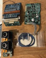
That is the IF box, I would like to make the audio inputs available, although it never ends up in a convenient spot.
The front plate will be untouched, the design is like someone else said "space age" and I really don't like unforeseen consequences of messing with things that already work nicely. I realized the dream of a speed booster will involve modifying the CCD unit more than the front plate. A bit shaved off the top and bottom, the rounded side sanded flat also.
The fat side of the camera will be all sony. The operator side will be a flat piece of carbon fiber. The back I am keeping the sony made fan mount, then the rest will be a sheet of carbon fiber.
The top plate will be on carbon fiber sheet. I am considering mounting a small cheese plate to accommodate for handles, although I might bolt handle straight to it.
The docks will save weight, they were heavy parts. The side panel saves a bit but like I said, Sony actually made their parts really light. The CCD Module is dark matter.
The really good news is I found a company that will CNC cut the carbon fiber sheets and drill out all the holes so I am treating the set a sheets I have as my first draft. Once I have everything set and working, I will send them the sheets I have and make a shiny new set with professional holes. Drilling, cutting, sanding this stuff is possible but not easy to keep it clean looking. I would like to make a few sets of these sheets so I can do a F23 Mini next. These sheets ain't cheap, but I really like the idea of getting the holes drilled professionally once it is all set.
In my testing I can sand the CF Sheet to a rounded corner so I am hoping the seams turn out alright.
Painting isn't out of the questions. I kind of like the idea of a cyborg paint job of all new parts and then the old sony grey mixed together.
Last edited:
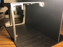
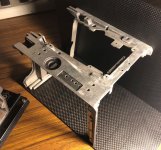
'm on the home stretch of reshaping the F35 skeleton. I'm gonna talk to a welding guy about reconnecting the base in a good manner but basically the base will connect to all the walls using these small L brackets so the skeleton becomes more of a guide for the load bearing carbon fiber sheets. I still want to make a straight post to fill the hole where the curved post was, I need something to hold the front corner of the camera together. If welding is out of the questions, a strong epoxy is going to work fine because this is more of a guide to holds the walls together. 3mm Carbon Fiber Sheet is VERY strong. I was looking at 5mm but I started with 3mm and it is plenty strong and has no flex.
Considering small things now:
1. Move A and B sdi ports to operator side front of camera. Add D tap near-by for EVF, 7Q off operator side.
2. Find place to add XLR plugs (I kind of like having the option) even if the 7Q has audio input of it's own. This board is necessary for the IF Box to send signal also so I can't save weight leaving it out.
3. The IF Box card placement. I have a few options. It's a little riddle. I have motherboard stand-offs, the same ones that work with any computer motherboard fit on the F35 boards. The plug that was the dock connector is huge. I am going to start routing the SDI A and SDI B to the genlock and SD SDI BNC Ports.
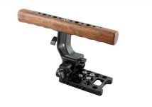
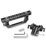
...the scene in the aviator when Howard Hughes can't decide on the steering wheel...I have spent so much on stupid camera top handles for my F35 and none are quite right and the whole point of this project is to make the F35 right.
I even tried F55 handle but the Sony EVF Mount built into handle is only good if you use Sony EVF, and mounting evf from the top handle at this distance is terrible on the neck. Call me crazy I never liked the original F35 handle at all, came from a different ENG age. I always thought the L handle was a cool defining part of the camera if not a bit oversized once you lost the SRW1.
I will probably get the wood one. I hope it isn't plastic wood. It isn't cheap at $200 but I can use the cheese plate to mount to top of the camera. There is something cool looking about the Smallrig one pictured also but I feel that is too C300 FS700. This is a silly thing to spend my time on but I also feel like the top handle becomes a very defining part of the camera in appearance and function.
Last edited:
fboonzaier
Well-known member
A short article for you on using fasteners with composites....carbon fiber is of course no exception...possible experimenting with different hole sizes for a given fastener and heatin it up to make sure there's no cracking around your fasteners. Indeed an admirable task on your part!!
http://www.melfast.com/blog/2015/06/why-fastening-carbon-fiber-is-such-a-tricky-process/
I just picked the first article that came up....you have probably looked into this already anyway!...used to build boats using epoxies...exotic but wonderful stuff to work with!
http://www.melfast.com/blog/2015/06/why-fastening-carbon-fiber-is-such-a-tricky-process/
I just picked the first article that came up....you have probably looked into this already anyway!...used to build boats using epoxies...exotic but wonderful stuff to work with!