New Blackmagic Camera July 16th?

I'm guessing that the design patent for ALEV - talking about the whole sensor - may be shared by several companies and Arri can't merely duplicate it in something completely new but can in the double LF and triple 65. In other words, it's not just the dual gain but wiring, manufacturing, etc. I am speculating because it seems a little odd that they have not come out with an entirely new sensor altogether in over a decade.

I assume they have tested a bunch of various projects but rejected them, given the cash cow that is LF.

PS. It also remains to be seen if the expected s35 4K camera is going to dip into the "affordable" sub-$40,000 territory. The high end market for the $100,000 LF's will run out of steam ... eventually.

The sensor was for sure their own custom design.

They consulted with a design house to fab this sensor.

The fab company stopped making their sensors a few years ago because they couldn't make enough money out of them. Arri had to switch to another fab that are now making their sensors. So two different companies have made Arri's sensors for them. (seperate from the design house that helped them design the sensor)

Dual gain isn't exclusive to Arri at all. it's just that it's REALLY HARD to do it well, so most don't bother. Why haven't Z cam done it for example ? Dual gain sensors are available...

https://www.electronicsweekly.com/n...sensor-approaches-90db-dynamic-range-2010-11/

This patent is from 1996
https://patents.google.com/patent/US6115065A/en

Onsemi like to claim they developed it
https://www.onsemi.com/blog/iot/image-sensors-academy-awards/

But they dind't, it was a company that OnSemi bought later on...
https://www.businesswire.com/news/h...-Leading-CMOS-Image-Sensor-Portfolio-Designed

Anyways, as I understand it, dual gain isn't an Arri Patent. Their other sensor tech that isn't seemingly out in the public domain yet is, but the dual gain part is not exclusive as I understand it. But the barrier is the engineering required to "make it work"

Anyone remember that Kinefinity were "doing" a camera that had very similar specs to the 4.6K ursa ? And it never happened ??

Dual gain is super hard. Only two companies have done it in cinema cameras... I think solving that engineering challenge is what drove BMD to make their own sensor design...

JB
 
Thanks, that link worked. The Vimeo footage looks great so I look forward to seeing the raw files.

You shouldn't just tease us about secret patents, but I guess you also can't reveal industry secrets. It is interesting that Arri's readout speeds were so far ahead of the curve (as regards rolling shutter and frame rate), and I understand the OLPF is an expensive one. Is the readout reversed for the LF and 65 so that it's reading out top to bottom and not reading out left to right?

I actually prefer the 3.2k Alexa to imagery from the LF and 65–there's a smooth quality to it and the noise texture looks better to me when it's a bit larger like that.

I assume the 12K lacks dual gain? Is dual gain very power-hungry? What artifacts can it result in? Softness? Ghosting?

What kind of resolution can I expect from the 12k relative to Bayer interpolation? I assume the white pixels take the place of dual gain in terms of boosting DR and increasing sensitivity–but is there a lack of color information in the shadows as a result?

It's an interesting way to look at it. If you were shooting film and it was very bright, you'd want a slower film (100 ASA) so you could open up the iris more. But with digital, to capture more highlights you would choose 400 ISO and add 2 stops ND.

Unfortunately I'm familiar with this. I bought some NDs for use with film and only needed to go up to three stops because I was expecting to shoot with 50D. But at least more and more digital cameras have internal NDs now.

I think there's a mathematical limit to dynamic range based on pixel size, something to do with full well capacity, but it's beyond me. But I think it's bizarro world once again–bigger pixels are bigger buckets with bigger capacities. Whereas Kodak's fine grain contributes to the highlight detail in its Vision 3 line. I could be wrong about this, it might cancel out somehow.
 
Last edited:
Cinema5D's DR tests are vastly more useful than the 21-step Xyla charts people are always posting as "proof" of 15/16/17 stop DR performance from various cameras, because they bring the readings into a waveform, and the waveform doesn't lie.

The point at which the darker stops (at the toe of the curve) disappear into the noise floor, is the point at which they cease to be "usable" stops. At best, those stops are faint details in the deepest shadows of the image.

Using the waveform to display this eradicates the need to argue which of those last few "stops" are usable - the waveform shows precisely where they become part of the noise floor. And that is the floor. It's really that simple.

People also need to get their heads around the concept of DR vs latitude. The spread of a camera's dynamic range above and below middle grey is what determines how well it'll handle the brightest highlights, and how quickly the shadows will fall off into unusable noise.

Just because two cameras might have a similar amount of overall DR, doesn't mean they'll be using it in the same way - so it's very easier to get more (or less) latitude in the highlights or shadows, depending on the gamma curves the manufacturer employs.

DR versus latitude is not the concept, it’s gamma versus latitude. Sensors are linear. There’s no middle gray, only middle IRE. You get different latitudes above and below middle gray by changing the gamma curve but the DR of the sensor is the same.

Example: You design a camera with 10 stops of DR with a gamma curve that puts middle gray at 1% IRE. You would have 10 stops of latitude above a very noisy middle gray but clipped everything below. You would not want to compare that camera to an Arri that had 10 stops of latitude above middle gray but also had 4 stops below. You cannot ignore overall DR to say that the number of stops above or below middle gray are all that matters.
 
The sensor was for sure their own custom design.

They consulted with a design house to fab this sensor.

The fab company stopped making their sensors a few years ago because they couldn't make enough money out of them. Arri had to switch to another fab that are now making their sensors. So two different companies have made Arri's sensors for them. (seperate from the design house that helped them design the sensor) ...


JB

Right but, let's look at it from a different POV. From the POV of the companies involved in the design. Or, to take it further, from an artist POV. Let's say you're Rockman Norwell or Libby Annowitz and you're hired to do a cover for the Rolling Life magazine. The contract precludes the Rolling Life from syndicating your work, meaning that the magazine is the end user, not a middleman and it can't further benefit from your work without the additional compensation. (or not at all)

In the sensor design case, it's very likely that all the companies involved agreed to let Arri manufacture as many sensors as they want but solely for their own use while prohibiting sales of the sensor to other manufacturers. The sensor, as a product, is defined as the result of all the research and innovation in its design. If someone has the idea of running the wire from left to right rather than from the bottom up, then it's part of the whole and can't be copied to a different product.

In total, ALEV is ALEV and it can't be carried over to another camera or another camera manufacturer. And, should part of a sensor named "ALEX" look too much like ALEV, Arri would be violating terms of the contract. Whatever "ALEX" might be and wherever it might appear, it will not be allowed to copy certain parts of ALEV design while others can be deemed outside of the protection. Of course, different from a painting or a photo, there can also be a time limit stipulation to the contract. After all, technology moves forward, patents expire, et cetera, et cetera.

Anyway, that's my take.
 
This is a long post, but I think I finally cracked the code on understanding and measuring Dynamic Range.


---


So, there is actually hard math for dynamic range and it's really easy to calculate - it's simply the ratio between the clipping point of the sensor and the average noise of the sensor.

The math is simply the 20log10 (voltage ratio) of the Full Well Capacity in electrons (clipping point) divided by the root mean square Read Noise in electrons (average noise).

So the math formula is just 20log(FWC/RN). Very simple, relatively speaking.

However, there are two problems with this approach.


---


One is that while the clipping point of the sensor is really easy to figure out, the average noise is absolutely not, at least while measured externally. Imatest's page on dynamic range has so much information that I have not seen elsewhere that explains the challenges in actually measuring DR: https://www.imatest.com/solutions/dynamic-range/

One huge takeaway is that even the tiny amounts of internal flare from lens optics absolutely affects dynamic range. That means that the dynamic range of a sensor, when paired with a lens, has an absolute limit (unless lens coatings get dramatically better) regardless of what the dynamic range of the sensor is actually capable of.

Imatest says that they have never seen anything better than about 16.5 stops of DR, even though there are sensors out there with a specified 20-25 stops worth of range. Simply adding a lens completely negates that higher dynamic range.

They also say specifically that dynamic range is improved by noise reduction. So, because of that, they recommend only using raw data that is stripped of any noise reduction and minimally demosaiced.

They say specifically that "Noise reduction can have a profound effect on DR measurements. In particular, SNR = 1, which is a criterion for the DR limit in some standards, may never be reached."

That means that noise reduction can prevent seeing where the noise floor is reached (SNR = 1 is where the signal and the noise floor is equal.) If you can't see the bottom limit, you have no way of actually measuring the average noise of the sensor.

So, yes, mathematically, comparing the highly processed and NR'd 5D Mk II to something lightly processed is not going to be a fair comparison.

On top of that, Imatest actually has their own alternative to the Xyla chart because of inaccuracies they measured on the chart itself. The much brighter initial steps were leaking into the rest of the image due to lens flare, causing an inaccurate reading. So, even though Cinema 5D is showing the noise floor, that noise floor may not be correct.


---


The second problem with calculating Dynamic Range is that measured dynamic range is considered something completely different.

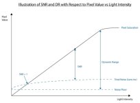
Measured dynamic range is not actually Dynamic Range at all - it is a similar, but separate concept known as the Signal to Noise Ratio, and it is that SNR number that we actually want to know, not the true Dynamic Range.

The discrepancy has come about from how a sensor engineer would define what Dynamic Range means versus what we would consider dynamic range.

To a sensor engineer, Dynamic Range, in sensor-land, is only a mathematical ratio between Full Well Capacity and Read Noise. It is not theoretical, it is hard math. You have two numbers and you look at the ratio between them and that ratio can only be one thing.

However, that hard number Dynamic Range does not include lens flare and it also does not include something called Shot Noise.


---


Shot Noise is an inherent characteristic for photons to follow a certain pattern, known as the Poisson distribution. This distribution means that less light levels equals a noisier image, regardless of anything else.

Basically, photons do not come all at once, hitting the sensor evenly, but come in a staggered way that creates noise.

The only solution to the inherent noise of light (you can't currently escape it) is to increase the full well capacity. If you are able to capture more photons, it spreads out that distribution and lowers the effect of that noise.

This website has a fantastic breakdown of all of this, including the chart I am listing below, which shows that SNR has less stops than actual Dynamic Range: https://www.lumenera.com/blog/under...-signal-to-noise-ratio-when-comparing-cameras

DRvsSNR.jpg

So, here is likely another reason why Arri's huge sensor elements (with likely massive full well capacity) have still won the day.


---


This explains a lot of things to me (and hopefully to you), including that there is a huge semantics issue when dealing with what an engineer would call "Dynamic Range" and what we would commonly refer to as dynamic range, but which is technically the Signal to Noise Ratio. I hope this leads to some future clarity when comparing cameras, and when dealing with manufacturers claims.
 
Last edited:
This is a long post, but I think I finally cracked the code on understanding and measuring Dynamic Range.

This is the greatest opening to a post ever.

the dynamic range of a sensor, when paired with a lens, has an absolute limit (unless lens coatings get dramatically better)

This is funny to read to someone who thinks lens coatings are already sometimes too effective for their own good. (Obviously, horses for courses)

However, that hard number Dynamic Range does not include lens flare and it also does not include something called Shot Noise.

I think there may be more types of noise as well that get introduced in reading and processing the signal. But that doesn't change the basic situation you're describing with regard to dynamic range of a sensor in theory vs practice
 
It looks better the way you graded it than the official releases. That's a good thing because it demonstrates the versatility of the BRAW file.

Also the 12k detail looks amazing, especially since I'm only viewing it on an HD screen proving that when HD isn't good enough it's because we're not making good enough HD.
 
Last edited:
I think there may be more types of noise as well that get introduced in reading and processing the signal. But that doesn't change the basic situation you're describing with regard to dynamic range of a sensor in theory vs practice

There actually is one more type of noise that comes from reading and processing the sensor. It's called Dark Noise or Dark Current Noise. Dark Noise is when heat in the signal path creates extra electrons that pollute the signal.

As you are probably aware, each sensor element (un-demosaiced "pixels" as they are technically not pixels yet) is simply gathering photons and changing them to electrons as carefully and efficiently as possible, so that those electrons can be counted further down the path.

Dark Noise is simply extra electrons added to that electron count, causing the sensor element to think it captured more light than it actually did.

Also, as it gets hotter, more thermal electrons are created and added to the signal.

So, you could be getting less SNR the hotter it gets.

This is why cameras have fans and complex cooling designs, in order to stop those spurious electrons from being created.

This is also why black shading is a thing on some cameras - if you want to remove that extra noise, you need to have a map of where it is, and that map is going to change the hotter the internals get.

This is also why hot pixels are called hot. Those pixels have dark noise much higher than the rest of the sensor, and dark noise is just heat, so they are literally hotter than their surroundings. I always thought hot was an analogy for brightness, but nope, you are actually seeing extra heat.

Here's some more info:

http://www.roper.co.jp/Html/roper/tech_note/html/tdark.htm

https://hamamatsu.magnet.fsu.edu/articles/ccdsnr.html

https://andor.oxinst.com/learning/view/article/ccd-blemishes-and-non-uniformities
 
Last edited:
Is there any tech brochure, white paper, or diagram on how the sensor pixel array is designed? So there's an equal amount of RGB pixels in the array, 1:1:1, in the same way a striped sensor on the Sony F65 has 8K pixels? In other words, are we talking about a sensor optimized for 4K RGB sampling and scaling? I would like to know a whole lot more about this sensor.
 
Here is also another explanation of Shot Noise (AKA Photon Noise, AKA photon shot noise): https://medium.com/hipster-color-science/photon-noise-4ecc95aae31d .

The author shows (with pictures) that "the darkest parts of the image have such a poor signal to noise ratio that you often don’t measure a single photon."

So, that is why you want a larger full well capacity (bigger bucket) so that you can collect as much light as possible to drown out the photon shot noise before you reach the upper limit of sensor saturation.
 
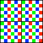
Here is what I'm pretty sure the sensor color filter array looks like:


RGBW6by6Large.gif


It fits John Brawley's description of 6x of Green, Red, and Blue (an equal amount of each), plus 18 White/Clear, on a 6x6 grid.

The magenta outline is to remind that each final pixel is actually calculated starting at the center of four sensor elements. At a very basic level, you would take 1/4 of each sensor element and average them together to make a pixel.

Now if you look at the center of each 4x4 group of sensor elements (picturing that magenta outline in the middle of those 4x4 groups all across the CFA) you'll notice that each 4x4 group is missing one color. This is actually not a big deal at all.

One reason is that modern demosaicing normally looks several sensor elements away. It's most likely averaging a much bigger area, even at 12K.

More importantly, though, is that you can actually determine the missing color by subtracting the other two colors from White. White, minus Blue, minus Red, equals Green and trice versa. (W-R-G=B and W-B-G=R).

For instance there are RCCB sensors (Red Clear Clear Blue) that claim to be better than standard bayer and they indeed do calculate Green by subtracting Red and Blue from Clear: http://image-sensors-world.blogspot.com/2013/07/aptina-explains-clarity-technology.html .

For credit purposes, I did get the pattern from this page of CFAs: http://www.quadibloc.com/other/cfaint.htm . On that page you can see two other CFAs that fit the criteria, including staggering each row or doing a row of GRB and then White, similar to the F35, but I doubt it is either of those approaches since it might not scale or be able to compute as nicely as this one does, and most importantly, would not be able to do subtractive color determination as well as this pattern does or at all.
 
The UMP 12K seems like a RED-killer to me. Or at least, it might lead to a role-reversal in the market.

If you're using a Monstro 8K, you're probably doing it for the resolution or because it's cheaper than an LF right? Now you have more resolution for less money and the vision looks great so far.

RED is doing something interesting with autofocus, but the best lenses don't have AF anyway. (Unless the camera can use the AF to drive the focus motor on any lens.)

So Komodo might become an option for OMBs who want to work in RAW. Though then it's competing against Canon who, for a bit more money, is way ahead in AF performance.

Obviously different cameras have different strengths, and the reported numbers don't indicate that the 12K has best-in-class DR. But maybe it will clear the decks of everything more expensive except Venice and LF.
 
Here is what I'm pretty sure the sensor color filter array looks like:

Very interesting, thanks for the analysis.

edit: this calculation down here is wrong, see correction below :(
Before this, my thoughts were: on a 6x6 block you have 6 red photosites instead of the usual 12, so the red channel at 12k will have the same resolution as a 6k bayer sensor, which is still very very high resolution

But the point that you can get green by substracting blue and red from white makes it even better! (I had seen the pattern graphs for those RGWW sensors but never knew how they got the missing color)
 
Last edited:
Wouldn't a Bayer sensor have 9R per 6x6? And the red channel will match the resolution of an 8K bayer sensor?
 
Very interesting, thanks for the analysis.

Before this, my thoughts were: on a 6x6 block you have 6 red photosites instead of the usual 12, so the red channel at 12k will have the same resolution as a 6k bayer sensor, which is still very very high resolution

But the photosites are half the size ? So you get 36 photosites where you used to only get 4 ? Josh’s great diagram above helps you visualise that...

So in the same AREA you get equal colour channels made by more pixels and you get white ones too.

JB
 
Last edited:
You are both right that I was totally wrong, but I think we can still do better than the comparison you suggest...

Let's try again:

If we compare this 12k sensor with a 6k Bayer sensor, for every old pixel you now get four smaller pixels covering the same area
a new 12x12 area with 24R, 24G, 24B, 72W, corresponds to an old 6x6 area with 9R, 18G, 9B ---> the much higher resolution definitely shows!

Comparing the new 12k sensor with an 8k Bayer sensor:
a new 6x6 area with 6R, 6G, 6B, 18W, corresponds to an old 4x4 area with 4R, 8G, 4B --> similar color resolution to an 8k sensor, but better distribution across R,G,B

Very nice sensor pattern, working thanks to the insane sensor resolution!

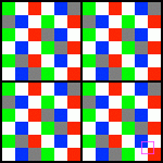
Now, I would still ask for a further improvement in future sensors: a 6x6 RGBWK pattern with 6R, 6G, 6B, 12W, and 12K photosites, where the K ones have no color but instead are covered by a neutral density filter absorbing, say, 5 stops of light. Could this allow us to get A LOT more DR out of the highlights of the image? (the current RGB tints allow something similar to this, but for just 1-2 stops of highlight recovery through clever debayering algorithms) (the K thing with 5 stops of ND makes the last 3 stops of recovered highlights totally monochrome, or at least very desaturated, unless even more clever algorithms are used to infer some color information)

edit: something like this:
RGBW6by6Large.gif
 
Last edited:
Back
Top