GH2 GH2 Power - specs, tests, DIY

Are you sure that's true of the GH2 specifically? It already does voltage monitoring to implement it's software-enforced 8.4V PSU cutoff point, so it may well monitor the battery V directly. And of course it wouldn't do this (or display it) if it thinks a PSU is connected..

I doubt it's a smart battery monitor, it's likely just a comparator setup or an UVLO (undervoltage lockout) circuit. I also doubt it's strictly software enforced either. Smart battery systems rarely work open loop, it's usually a combination of battery controller and charge controller working in a closed loop with each other. They are designed to work independently from the system they power as a safety feature so that no software glitch can cause runaway charge cycles which would cause damage and possibly fires.

Generally smart chargers count columbs of charge independently of what the GasGauge says the battery is charged to. While the battery reports a "calibrated" charge percentage, the charging IC only really cares about alert flags from the battery controller. Alert flags are either warnings or some other battery status. The charging IC or host controller on the I2C/SMbus can also interrogate the battery for its status as well. Either way, the GasGauge reading is usually fairly close to the actual % charge.

Did I read that the camera body does NOT give you shutdown warnings when using 3rd party batteries? Smart batteries will send out an alert with low battery warnings at pre-determined levels of charge, I'm wondering if the body gets all of it's all of it's low battery warning from the battery itself. It seems like it should as there would be no point in having some kind of secondary voltage watchdog in the camera. This would explain why the cameras offer no shutoff warning.
 
I totally agree. We need to know what regulator is used so we can find out the safe upper voltage. Check out the circuit board Svart, can you spot the part? I tried but the scans aren't high-res enough.

EDIT: Few more pictures here.


in this pic:

http://www.chipworks.com/media/wpmu/uploads/blogs.dir/4/files/2011/01/Untitled-7.jpg

it's the one on the bottom right.

It's surrounded by inductors so it's obvious that it's a switcher that produces many voltage rails.

It's common for these types of supplies to have UVLO(under voltage lock out) so that you do not have sagging voltage rails to the ICs when you try to power it from a supply that has insufficient voltage. They can accept a range of voltages usually though.

However, the part looks unmarked in the pic. Not sure if that's just a picture thing or if it's really not marked, but I've seen that before with proprietary ICs. Chances are good that it's a panasonic part made specifically for powering that family of processors. Not good odds of getting info on it though.
 
Last edited:
I doubt it's a smart battery monitor, it's likely just a comparator setup or an UVLO (undervoltage lockout) circuit. I also doubt it's strictly software enforced either. Smart battery systems rarely work open loop, it's usually a combination of battery controller and charge controller working in a closed loop with each other. They are designed to work independently from the system they power as a safety feature so that no software glitch can cause runaway charge cycles which would cause damage and possibly fires.

The GH2 body doesn't charge batteries though.

Did I read that the camera body does NOT give you shutdown warnings when using 3rd party batteries?

I read the same. It sounds like the 3rd party batts just pretend to be DC adapters, I assume they have to have another cell to output more voltage. If so, then there's no reason for the body to issue any warning as it doesn't expect the voltage to change.
 
It doesn't necessarily have to charge a battery to use a smart charger IC.

However, We don't know what that big IC is, it could have a full battery management system in it or it could just be a dumb power supply. It's obvious though that the unit can determine that a battery is present and what the charge % is. The SMbus(serial communication for battery status) is probably directly controlled by the CPU and the thermistor connection is likely connected to the power controller IC(in that picture).


LI-ion batteries have safety circuits to cut their outputs off in the case of over/under voltage. Even the cheap ebay ones have this at least.

So yeah, the 3rd party batteries just look like DC adapters so the body doesn't expect the sudden cutoff of the battery pack one it reaches it's lowest safe voltage and turns itself off.
 
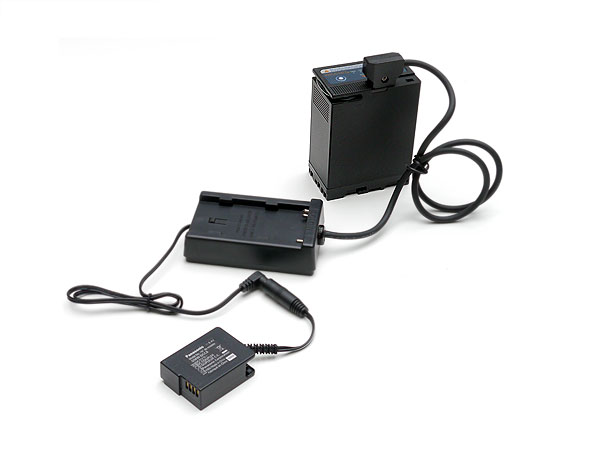
Hmm, the problem of using large capacity external batteries (DV batteries, 12-14V, etc.) is already solved, we are shipping the Power Plate which can be ordered in different flavors depending on what kind of a DC power source you want to use. Getting a hold of a DCC8 adapter off course is still a problem at this poing :-(

Thanks for sharing this! Didn't even know that was out there! I'll definitely be saving up to buy this at some point! looks like it would make a great counterweight on the back of a shoulder rig. One question: there is an option when ordering for "output 2 configuration". what is this, an extra output? what for? (what could it be used to power. it is 7.4v as well?)
 
...the additional pins are not required to simply power the body, as Roberto claimed.
Misunderstanding. I was saying the extra terminals show there's more going on than just powering the body. ie, don't mess around until you know what you are doing.

Call me conventional, but I rarely get out the soldering iron until I've sketched out a circuit. I haven't seen a circuit diagram on this thread! I hate to hear of fellow users just putting their shiny new GH.x to the smoke test!

Now, you wouldn't start shooting a movie with your GH.x without a script, would you?

I do realise this thread is for readers prepared to mess with their equipment. So, here's my parting comment - a standard, "Don't do this at home" spiel:

Unless you're quite happy to fry your camera, leave the electric bits up to Panasonic (who will respect your warranty) -or folks like Dolgin, who will be legally obliged to replace your camera (in most countries) if their accessories stuff it up.
 
Last edited:
Misunderstanding. I was saying the extra terminals show there's more going on than just powering the body. ie, don't mess around until you know what you are doing.

We know what we are doing, we are simulating the DC PSU which is fully understood and doesn't use the extra pins. However we don't know the safe upper voltage limit, which is why I'm using a regulator to supply the same voltage as the PSU. I'm personally not happy cramming in a higher voltage until it's confirmed safe.
 
Thanks for sharing this! Didn't even know that was out there! I'll definitely be saving up to buy this at some point! looks like it would make a great counterweight on the back of a shoulder rig. One question: there is an option when ordering for "output 2 configuration". what is this, an extra output? what for? (what could it be used to power. it is 7.4v as well?)
In case you are looking to power an audio recorder or a small monitor with the same battery, the additional cable will allow for that. That extra device will have to be able to run on native DV battery voltage, which is commonly called 7.2V. In fact it varies between 8.4V and 6.5V as the battery is discharging from full to empty.
 
The battery is 4500 mAh. I'm updating the first post with this info too. Can't believe I forgot to include that bit of info!

View attachment 34395

http://www.amazon.com/Speedpack-450...e=UTF8&s=toys-and-games&qid=1306180452&sr=1-2

I looked at the Amazon RC pack data sheet, it is a 7 cell NiMh battery.

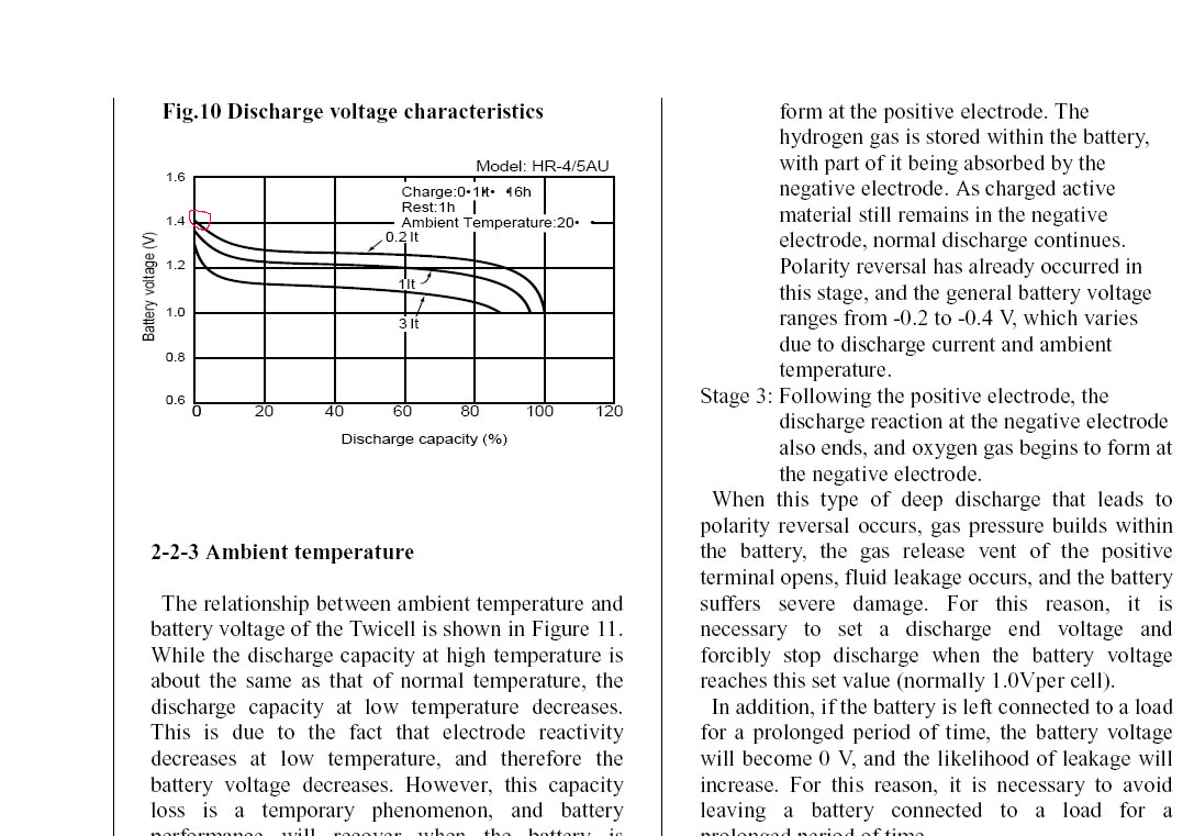
NiMh-cell-voltage.jpg


This is the voltage discharge curve for a typical single NiMh cell. The 7 cell pack that you use will have ~1.4V x 7=9.8V when fully charged (I highlighted the starting point of the discharge in red). In other words, the GH2 camera that is nominally designed for ~8.4V - 9V DC power is seeing ~10V every time a freshly charged NiMh pack is connected. Keep in mind that the graph shows a slightly loaded cell at .8A. In the case of GH2, that voltage is going to be even higher as the camera uses ~.3A to operate, or zero when turned off. NiMh cell voltage varies a lot depending on load, temperature, and charging.
 
The 7 cell pack that you use will have ~1.4V x 7=9.8V when fully charged (I highlighted the starting point of the discharge in red). In other words, the GH2 camera that is nominally designed for ~8.4V - 9V DC power is seeing ~10V every time a freshly charged NiMh pack is connected.

Here's a repost of my battery test I originally posted in another thread, which jives with your research:

I used my DIY DWM-DCC8 adapter for this test.

There have been questions about the viability of using an external 8.4v battery with the GH2. I hope the following video answers those questions.

I did a timelapse of the GH2 hooked up to an 8.4v rated battery AND a meter, to show what exactly is happening over time. The camera stayed on for just over 8 hours on a single full charge of the 8.4v battery.


Here are the details: For almost 7 of the 8 hours the camera was recording at 720p. (I had to twice stop and delete the recording to free up space. This was done without turning anything off.) The LCD was on the whole time. The interval of the timelapse was 1 frame per minute.

The battery actually metered 9.93V before I started, but dropped quickly to 9.84v once I got the camera on and recording. Also interesting to note is that the camera shut off at 8.37v and the battery went back up to 8.64v. When I got back to check the test, I turned the on camera and the voltage dropped to 8.41v and displayed "this battery cannot be used" on the screen before shutting off.
 
Last edited:
An interim summary of the GH2's power circuitry:

1. Minimum voltage (via internal battery): still undetermined, but probably around 6.6 volts. Could be as low as 6.0 volts.

2. Minimum voltage (via DCC8) - 8.4 volts (http://www.dvxuser.com/V6/showthrea...cs-tests-DIY&p=2345617&viewfull=1#post2345617)

3. Maximum voltage still undetermined, but users have reported up to 10 volts as safe: (http://www.dvxuser.com/V6/showthrea...cs-tests-DIY&p=2341044&viewfull=1#post2341044

4. Max average power draw (from spec sheet) is 3.4 Watts. This is confirmed by Badpix (http://www.dvxuser.com/V6/showthrea...ts-DIY&p=2327768&highlight=badpix#post2327768) who powered the GH2 at 9.15 volts with current readings that ranged from 350-410 mA. Taking the average at 375 mA yields 3.43 Watts. The GH2 circuitry is assumed to be constant power, driven internally by switching circuits (see point 10).

5. Maximum current draw is about 800 mA under two conditions: at turn on, and immediately after using the flash (http://www.dvxuser.com/V6/showthrea...cs-tests-DIY&p=2329479&viewfull=1#post2329479)

6. To power the GH2 externally requires a power supply that can provide 8.40 volts at 800 mA. Including a factor for margin of error, suggests an external AC supply should be rated at 8.6 volts DC at 1.0 Amps.

7. Running the GH2 from external batteries without a switching regulator means using 7 NiMH cells. Any more and the initial voltage when freshly charged may damage the GH2. This method is easy to implement (no additional circuitry), but is inefficient – you need a larger battery than expected. For example, Keylight powered the GH2 for 8 hours from an 8.4 volt, 4500 mAh pack. If all the battery capacity could have been used the run time would have been 11.5 hours ( assuming 3.4 Watts drawn at an average voltage of 1.25 volts/cell the average current is ~390mA, giving a theoretical runtime of 4500/390 = 11.5 hours). The inefficiency is due to the 8.40/7 = 1.2 volt cutoff (instead of the 1.0 volt cutoff used by the manufacturer when measuring the capacity).

8. By using a battery supply with higher voltage, and regulated by a switcher set to ~8.60 volts, almost all the battery power could be used, though ~10% of the energy would be lost in the switcher. Using 10 Eneloops, for example, (1.25 volts/cell, 2000 mAh), would yield a run time of about 6.5 hours. The disadvantage is – a switcher is required.

9 An optimum solution for external power would be to use a chip such as http://products.cui.com/adtemplate_...p=46094&c=194683&catky=&subcatky1=&subcatky2=, embedded inside a DCC8. Such a solution would run from 11-32 volts at about 90% efficiency, and be short-circuit and thermally protected. An input diode may be required to protect against reverse voltage.

10. The info on this page (http://www.chipworks.com/en/technic.../2011/01/teardown-of-the-panasonic-lumix-gh2/) says that one of the power supply chips is a Rohm BD8963EFJ (http://www.rohm.com/products/databook/power/pdf/bd8963efj-e.pdf). This chip is a switcher (up to 88 % efficient) which provides 1.0 - 2.5 volts output from a 5 volt (typical) input. Absolute maximum input voltage is 7.0 volts, suggesting that between this switcher and the GH2's power terminals is additional circuitry that regulates/protects the voltage delivered to the GH2. Internal RAM (http://www.elpida.com/en/products/mobileddr2bare.html) requires 1.8 volts, suggesting it is driven from the Rohm switcher.

11. To simulate the effect of the GH2 on a power supply without having to connect a GH2, use a 10 ohm, 5 Watt resistor in place of the GH2. If the voltage stays above 8.4 volts, the power supply will almost certainly work when connected to the GH2. If you intend leaving the resistor in the circuit for more than about 10 seconds, use a 10W resistor, not a 5 Watt, otherwise it may begin to smoke.

3rd-Party Battery
I have pulled apart my third-party battery. Well, there goes the delusion I had of being able to add a simple circuit into a DCC8 to make the GH2 think a battery was in place. As well as two batteries in series, the battery case contains a small circuit board packed with components: 15 resistors, 10 capacitors, 5 transistors, 3 ICs, 1 inductor (marked 220), and 1 saw mark where I opened the case and partly sawed through one of the ICs. I'm not going to bother to try and trace the circuit. High-resolution images of both sides of the board and the two batteries can be downloaded from: http://www.mediafire.com/?4b21y4sy55gx61u
 
Last edited:
FYI, DMW-DCC8 Now in Stock at Adorama

FYI, DMW-DCC8 Now in Stock at Adorama

Just a quick note....

The DMW-DCC8 adapter for the GH2 is finally in stock at Adorama. I forgot I had one back ordered (from several months back) and they sent me an email telling me it shipped.

I might crack it open once it arrives, to take photos and see if there's anything special going on inside.....

OH YEAH!!! Just ordered 2 and they have already been shipped.

Mark
 
Great summary guyburns.

I got a reply from Chipworks, but they weren't able to help without performing lab tests (which costs). The regulator IC does seem to be proprietary, or at least unmarked.

I've also been running my camera with the Texas regulator at 8.6V for a few days - it works fine with a short cable (~50cm) but it failed today with a 3m extension connected. I will measure everything shortly, but it looks like the 8.8V from the official PSU is a better bet. I'll also test a 10m extension.
 
Last edited:
I think it it safe to run the camera in the 9 to 10 volts range.
As I mentioned before the GH1 adapter is rated at 9.3 volts.
As stated on this page, the camera turns off at 8.37V, so there must be at least 0.5V safety margin.
 
As I mentioned before the GH1 adapter is rated at 9.3 volts.

We don't know for sure that the bodies use identical power (but I agree it's likely). Have you actually measured the GH1 PSU output? That would be interesting.

But you're right that there is a tolerance anyway, because the PSUs vary a little. Anyone know what a realistic tolerance percentage is?
 
The external power supplies won't vary much at all, especially switchers. Maybe hundredths of a volt from unit to unit.

The power supply in the cameras, and others like it, have input ranges so that designers have some flexibility in their usage. Because it's a switching device, the theoretical minimum input voltage is not much more than the maximum output voltage(accounting for some drop through the circuit, etc). However, most companies put arbitrary limits on the inputs through software or hardware.
 
Back
Top