
Navigation
Install the app
How to install the app on iOS
Follow along with the video below to see how to install our site as a web app on your home screen.
Note: This feature may not be available in some browsers.
More options
You are using an out of date browser. It may not display this or other websites correctly.
You should upgrade or use an alternative browser.
You should upgrade or use an alternative browser.
F35 focal reducer/speed booster mod
- Thread starter Hunter Hampton
- Start date

Hi Hunter,
I'm not sure if this has been covered elsewhere, and if it has, I'll just delete it. But after several reads, I'm not sure if it's clear to everyone how the speed-booster works, and what the underlying pre-requisites are for its ability to make a brighter picture.
Although I have no personal contact with the metabones team, the concept behind the speed-booster is simply to change the total optics characteristics to focus a smaller image onto a given sensor. This is what makes the final image brighter - the light is being concentrated into a smaller area or circle. If you reduce the radius of the final image by Sqrt(2), the brightness will increase by a full stop (same math as applied to the inverse-square law for lighting). For example, if you have a lens that makes an image circle radius of 1.7 inches, and then add an adapter that shrinks that image down to a circle radius of 1.2 inches, (a reduction of only 1/2 inch), the brightness in that circle will have doubled, gaining 1 stop! Note that for a 1 stop gain you are working with a lens that has a crop value of 1.4 for that sensor.
So if you have a taking lens designed to fully cover a 35mm full-frame, it will have a circle radius of at least 21.8mm and area of 1490 sq-mm. If you have a sensor for the Black Magic Pocket Cinema Camera (BMPCC), its circle of coverage needs to be no less than 7.2mm, and have an area of 161 sq-mm. Theoretically, one could boost the brightness of the 35mm full-frame lens by 9.2 times if it were to be reduced to fit the BMPCC sensor. (Area of lens/Area of circle over sensor = theoretical max gain brightness if area of lens can be matched to that of circle needed to cover the sensor).
However, the real world is different from theory. Keeping the image perfect, while bending all light into a much tighter circle is one challenge. Changing the mounting setup for the sensor would be the other, as the focal distance gets considerably shorter the more you shrink the image-circle. This may have been the most difficult thing for metabones to overcome, and may be an area where custom front ends on the F35 could more easily overcome.
But despite the possible gain of 3.2 stops for this setup, Metabones can "only" gain 1 2/3 stops, and take the crop from 3 to 1.75, when going from a full-frame 35mm lens to an image sensor that can be completely covered by a 7.2mm radius circle. So physical/economic limitations do exist.
If you look at metabones data on their adapters, you'll see they don't get their adapters down to a crop value of 1 - presumably because of these limitations. For the M43 converter, they take the picture circle down just far enough to give them a crop of 1.42. Even though an M43 sensor can use a picture circle as small as 10.9mm radius - and could have a theoretical gain of 2 stops from a full-frame 35mm lens, their adapter goes no smaller than 15.3mm radius, allowing for "only" 1 stop gain. I point this out to show difficulties with reaching theoretical performance.
If one were to try and make gains on a full-frame 35mm lens to the Sony F35, the total theoretical gain in brightness would be 1490 sq-mm /584 sq-mm, yielding 2.55 or 1.35 stops. The fact that the theoretical gain from full-frame to M43 was 2 stops, but metabones only gained 1 stop, might make one pause to consider the potential difficulties of getting even 1 stop gain on the F35. If physical conditions can only achieve 1/2 of the theoretical, starting with 1.35 stops theoretical gain may not be worth the struggle.
However, if you were to start with lenses designed for much larger image circles, you could gain a lot more brightness - if the larger format lenses started at the same f numbers as the full-frame lenses do!
Take, for example, a Bronica 75mm f/2.8. It's image circle radius would be larger than 42.5 mm, with a minimum area of 5,674 sq-mm!!! If divided by the F35 image circle of 584 sq-mm, we see a theoretical gain of 9.7 or 3.3 stops!
Getting all that glass perfectly positioned opposite the sensor might be a challenge, but even if you sacrificed that number by half, you'd still make tremendous gains.
An easier way to estimate light gains is to divide the radius of the image picture - created by a lens - by the radius of the image circle needed to fully encompass the sensor. Then square your answer.
For instance, a typical full-frame 35mm lens creates an image circle radius of 21.8 mm. The Black Magic Cinema Camera has a sensor of dimensions 15.81mm x 8.88mm, needing an image circle radius of 9.07mm.
So we take 21.8 / 9.07 = 2.40.
Now, 2.40 squared equals 5.76.
Possible gain in brightness is 5.76 or 2.5 stops. Metabones achieves 1 1/3 stops. Their crop factor is 1.53. Crop is calculated by dividing radius of taking lens by radius of image covering sensor. For BMCC, a 35mm full-frame lens experiences a crop of 2.4. If metabones could have reduced the crop down to 1, they would have gained almost 2 1/2 stops.
Interestingly enough, if you know the crop value of a lens to a sensor, you can simply square that number (ie. square 2.4 is 5.76) to get the light magnification possible if the "perfect" adapter could be made for that lens. In this case, max possible gain would be 2.5 stops.
That said, trying to speed boost a Cooke Pancro, for instance, with an image circle radius of around 15.6 mm, to the Sony F35 sensor (covered by radius 13.64 mm), you get a max theoretical gain of 0.20 stops. No point in even trying to speed boost that.
Last edited:
keithlango
Well-known member
^^^^
TL;DR:
Take that money and buy a truck of used Mole Richardson Fresnels.

No, seriously great info, Sandbox. Thanks for sharing all that science. I feel smarter just being in the same room as you.
TL;DR:
Take that money and buy a truck of used Mole Richardson Fresnels.
No, seriously great info, Sandbox. Thanks for sharing all that science. I feel smarter just being in the same room as you.
LeavingTheCandy
Well-known member
Good info, but my brain hurts now.

Hunter Hampton
Carbonite Member
Great info Sandbox- Yeah I was talking about mainly "speed boosting" 35mm slr lenses, or rehoused 35mm PL lenses- I think your right about the FFD being an issue or needing adjustment.
Based on your post, I have some new ideas for taking medium format lenses and shrinking down the image circle to super35mm- that might get us some very fast lenses no? Basically what I really want is an affordable sharp 0.95 to be able to use on the f35 in certain night scenes.
Based on your post, I have some new ideas for taking medium format lenses and shrinking down the image circle to super35mm- that might get us some very fast lenses no? Basically what I really want is an affordable sharp 0.95 to be able to use on the f35 in certain night scenes.
keithlango
Well-known member
The E. German Zeiss Jena Pentacon 6 lenses are medium format, some of them reasonably fast at 2.8, too. Taking the 30mm 3.5 Zodiac Pentacon 6 and speedboosting that would be an interesting experiment if it could be done. I don't know the math, but even if you could get an extra stop down to f2 and widen it up to 25mm or so you'd have a very workable solution. And the mount can stay PL, too.
Allstar has a hasselblad-pl adapter which may play a nice role in our goal. Possibily contract metabones to create a hasselblad speedbooster? Could mean $$$ to them, and a whole new portal of fun for us!
http://allstar-cine.myweb.hinet.net/html/red_accessories/A_M_adapter.htm
https://vimeo.com/42560661
http://allstar-cine.myweb.hinet.net/html/red_accessories/A_M_adapter.htm
https://vimeo.com/42560661
Think of the medium format lenses (for the F35) as the equivalent of going from 35mm full-frame lenses down to a BMPCC sensor! Lots of room for gain. 3 stops plus, in fact. That would get a 2.8 down past 1 in a perfect world.
Getting those gains, however, will mean getting the crop factor down near 1. And doing that without introducing aberration might be a challenge - but there may be a work-around for that, too, if you're crazy. And because you're already talking about taking the lens mounting plate off the F35, your freedom to move glass closer to sensor will give you much more freedom than metabones had with their product line. So there definitely seems to be a chance with this option.
Regarding potential aberration issues - there was an article about cameras of the future handling aberration and other lens-related issues by processing the image in-camera, so that the need for expensive lenses could be done away with.
The proposition was that as long as the camera "knew" what the deficiencies of the taking lens was, and could manipulate the pixels back to where they needed to be, prior to recording them, the camera could capture imagery just as sharp as a perfect lens, but using a single element plastic lens instead.
If you think about it, light's behavior is mathematics, and if you know where a lens is failing to keep things lined up, and you sample it sufficiently, you should be able to apply formulaic corrections to the picture prior to recording it.
This got me thinking of the possibility of fixing image degradation caused by using "inexpensive" lenses or, in this case, an inexpensive optical adapter (which may be a problem, as a "perfect" solution might cost thousands).
Each adapter/lens setup could, theoretically, be "diagnosed."
You could begin by capturing footage of a detailed black and white grid, and import a plate into an application like Nuke, where one could not only correct distortion, but manipulate each color channel independently, using warp maps, until all the pixels line up to give a sharp, clean image.
Lens distortion could then be re-introduced, but the picture could be pristine if done right. And each solution would stay married to that lens/adapter combination forever (assuming we're talking about primes).
Now I haven't experimented with it myself, and there might be other variables introduced by changing F-stops. But if you're using an adapter, it's probably for a particular application, and probably wide-open, so I think the possible variables could be ignored.
Once the lens setup is evaluated and solved, all footage shot with that setup could be fixed with this solution effortlessly. And workflow wouldn't even require the image to be "fixed" until final edit, just before going into color. So I don't think it would hurt workflow that much, while offering quite a gain.
This is assuming that bringing an image from crop-factor of 3 to crop factor of 1 is going to bring some optical difficulties. If the adapter can handle all this without degradation, then I'm just wasting your time with another TL/DR
keithlango
Well-known member
VFX butters its bread with pre-baked recipes for everything from CG lighting solutions to color correction to pre-comps to...well, anything you can imagine. Adding a lens correction recipe would just be another log on that fire and would slot pretty seamlessly into any given pipeline. I recall a few months back reading about somebody who released an After Effects comp file that emulated a 40mm Anamorphic lens. Distortions, blurs, vignette- the whole shebang. This is pretty straight forward stuff, really. The thing that's really hard to do in post is make soft images sharper. That requires a bit more magic sauce than your typical VFX production artist possesses. You need straight up optical engineering algorithmic programming help, and even then results are sketchy. If it were easy it'd already be a plug in for Photoshop.
In other news Dave's been designing an interchangeable lens mount system for me because he's the man (ie. a system allowing mount swaps without having to remove the front plate) to switch between PL, Nikon or EOS by changing a few screws on the front and also giving a lot more room around each lens. I'll update as it progresses, probably in a new thread. Exciting times!
as a non-current, but hopefully soon to be F35 owner, this sounds like a dream. just figured I'd share some more outside interest in this
revisiting an old idea. So I broke a speed booster (by accident) in e mount and took it apart today.
After looking at the glass part and the space inside the F35, i am sure it would fit.
The good:
The speed booster has a sleeve around the glass module. This sleeve can screw/unscew to fine adjust the position of the glass. The distance this sleeve can hold the glass is great, probably 2 cm between extremes. What this means that mounting the sleeve should be easy to the back of the front plate. After the sleeve is mounted, it would be simple to roll the speed booster back until back focus is good. There is a small set screw which holds the glass in place. This is hard to explain but basically the part of the metabones is setup perfect to mount to the F35 plate with some simple modifications.
The Bad: The IR filter needs to go to fit the back of the speed booster. The back glass of the speed booster is flat, perhaps an IR filter could be attached to the back of the speed booster. In any case, it's possible but more complex and requires removing the IR filter which exposes the CCD.
The Ugly: The Nikon mount will be even further into the camera. This means I need to destroy the PL mounting screws in order to make the hole wide enough to accommodate the back of the lens. The iris ring on small primes like the Samyang will be buried inside the camera body. It is a bummer to destroy the PL mounting holes because one of the great things about my current Nikon mount is I can put the original PL mount back on the camera.
I am more interested in this project after seeing that the part does fit into the CCD unit, hopefully I can have some results to share within the next few weeks.
Can anyone verify that the IR filter distance from the sensor can be changed without ruining its purpose? My current plan relies on being able to set a new IR filter slightly behind the speed booster.

macgregor
Veteran
revisiting an old idea. So I broke a speed booster (by accident) in e mount and took it apart today.
After looking at the glass part and the space inside the F35, i am sure it would fit.
The good:
The speed booster has a sleeve around the glass module. This sleeve can screw/unscew to fine adjust the position of the glass. The distance this sleeve can hold the glass is great, probably 2 cm between extremes. What this means that mounting the sleeve should be easy to the back of the front plate. After the sleeve is mounted, it would be simple to roll the speed booster back until back focus is good. There is a small set screw which holds the glass in place. This is hard to explain but basically the part of the metabones is setup perfect to mount to the F35 plate with some simple modifications.
The Bad: The IR filter needs to go to fit the back of the speed booster. The back glass of the speed booster is flat, perhaps an IR filter could be attached to the back of the speed booster. In any case, it's possible but more complex and requires removing the IR filter which exposes the CCD.
The Ugly: The Nikon mount will be even further into the camera. This means I need to destroy the PL mounting screws in order to make the hole wide enough to accommodate the back of the lens. The iris ring on small primes like the Samyang will be buried inside the camera body. It is a bummer to destroy the PL mounting holes because one of the great things about my current Nikon mount is I can put the original PL mount back on the camera.
I am more interested in this project after seeing that the part does fit into the CCD unit, hopefully I can have some results to share within the next few weeks.
Can anyone verify that the IR filter distance from the sensor can be changed without ruining its purpose? My current plan relies on being able to set a new IR filter slightly behind the speed booster.
:beer::beer::beer::beer::beer::beer:
Rick LaLonde
Active member
Was it ever determined that the front plate can be modded to an E-mount?
keithlango
Well-known member
Was it ever determined that the front plate can be modded to an E-mount?
Not 100% certain, but I would doubt it's feasible with a simple front plate mod. The Nikon F mount mod sits pretty much right in the metal of the front plate and not out in front of it like the PL does. And the Nikon's flange distance is a roomy 46.5 mm. A Sony E-mount's flange distance is a slim 18mm, which (based on what I remember of the spacing of things inside the F35's front) might actually put the mount inside the optical block, or at least so deeply recessed as to be unusable in any practical sense.
You might could get the plate modded to a Canon EF mount, though. It's only a few mm closer than the Nikon and so might be able to be machined into the front plate. Of course I could be wrong, so double check my math.
Rick LaLonde
Active member
Thanks, Keith. Yes, The E mount FFD is 18mm. When you say 'optical block' is there something in front of the sensor? I know the F23 has the 3CCD prism system but I've never heard of anything between the sensor and lens mount on the F35. As you can tell I don't have one to look at.
-Rick
-Rick

jenningsp
Well-known member
Yeah the sensor block has a built in glass piece almost exactly 20mm from the sensor. i cant remember if it's an OLPF or a UV/IR cut filter or a hot mirror of some kind. but it's something. and is a part of the sensor block.
To do this, you would have to completely make a new front plate and remove/move this filter.
To do this, you would have to completely make a new front plate and remove/move this filter.
keithlango
Well-known member
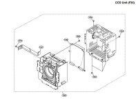
Sorry, "optical block" was a poor word choice. I'm refering to the CCD unit, the square-ish sub-assembly that holds the sensor and associated electronics which is bolted to the back side of the front plate. The sensor itself is recessed fairly deeply into this unit, so any mount adaptation that has a flange distance shorter than 40-ish mm will need to rest somewhere behind the front face of the CCD unit itself. Who knows what electronics or bits & bobs would need to be relocated or re-engineered into new places for that to happen. I've never had the guts to tear a CCD unit open, and even Sony only sells them as fully intact units (as you can tell from their parts # delineation in the exploded view schematic). You can't even buy parts for the CCD unit, you just buy a new CCD unit (ah, the things one learns the hard way. *sigh*). Anyhow, even if one were intrepid enough to try and put the mount onto the CCD unit, the flimsy metal shielding of the CCD unit would end up supporting the weight of the lenses. Never mind how you would adjust aperture way back down in there...
Rick LaLonde
Active member
Ah, that'e the full picture. Yeah, that would be major surgery. Too bad.
I was hoping for a route to getting my PL anamorphics on the F35 with a speed booster in between in order to get the lost field of view. As you probably know the only PL option is to E mount.
Thanks again and especially for posting the exploded view!
I was hoping for a route to getting my PL anamorphics on the F35 with a speed booster in between in order to get the lost field of view. As you probably know the only PL option is to E mount.
Thanks again and especially for posting the exploded view!