Honda EU3000i generator

drcheese

Well-known member
Hi, I'm working on a shoot this weekend, and someone just pulled out a Honda EU3000i generator to use for lighting a night scene (probably to power just a couple 1ks). I'm new to the world of generator lighting, and I was wondering if there are any issues I should be aware of. I'm pretty sure sound would be an issue if I don't place it far away, but is it possible I can do any damage to my lights? What if I decided to use a 1200w HMI with electronic ballast on it? Anyone have any experience with this generator? I see the EU3000is mentioned on the site, but I think the s just means silent?

Thanks for any help!
 
The EU3000i is an inverter based putt-putt. This means that it generates DC that is fed into an inverter that synthesizes the AC waves. You get rather perfect 60hz and fantastic voltage regulation. The wave is generally quite clean and does not rely on engine speed control to determine the frequency. 1.2k HMI are no problem, computers are no problem, cameras are no problem.

Carlos
Solid Camera, Inc.
 
Great product. If you know you are going to throw larger starting loads on it, shut off the idle option and let it take the startup load at full boogy.

Grant
 
I've got an EU3000is. Very nice, quiet little generator. But let's be clear about something -- there's nothing "silent" about it. Sure, it's quiet for a generator, but it's still really loud. Just not as loud as a normal generator. The only way to make it "silent" would be to turn it off. :thumbsup:

For comparison -- a DeWalt DG3000 generator (non-blimped) outputs 74dB of noise level at idle. The Honda outputs 49dB at idle. So that's a difference of 25dB, which makes the DeWalt about 16x louder than the Honda, a huge difference and why the Honda is known as a quiet generator.

But it's still 49dB! That's about as loud as if someone was having a full-volume conversation (not whispering, but talking at full volume) right next to you.

So it's quiet for a generator, definitely. But silent? No, far from it. The only "silent" generator is a battery. :thumbsup:

But that's the EU3000is. The EU3000i appears to be the newer/smaller/more portable "Handi" version. MUCH lighter -- it's 78 pounds, vs. the EU3000is's 134 pounds. Built-in wheels so it's more portable. And less expensive. But it's a lot louder. It's 57 to 65dB, vs. the EU3000is's rating of 49 to 58. That puts it at 7 to 8dB louder, so 2.25 to almost 3x louder than the EU3000is.
 
Last edited:
…1.2k HMI are no problem…

Barry is right, even a “silent” generator makes noise. The problem with 1200W HMIs and portable generators, even the super quiet Honda Inverter generators, is that by the time you move them far enough off set that you don’t hear them you have significant voltage drop from the long cable run back to set that can cause problems with non-Power Factor Corrected (PFC) 1200W Electronic Ballasts. To the problem of line loss, you have the added problem that as you add load, the voltage drops on portable generators. It is not uncommon for a generator to drop 10-15 volts under full load. The combination of voltage drop on the generator and line loss on a long cable run can cause voltage to drop to the point where you do have problems with 1200W HMIs with electronic ballasts: at low voltage a 1200W electronic HMI ballast will likely overload the generator’s 20A circuit, your AC extension, or won’t strike at all. Why? Because, a 1200W HMI with non-Power Factor Corrected (PFC) electronic ballast will draw a lot more than 1200Watts.


ArriEBL1200_Ballast_Nameplate.jpg


Manufacturer’s nameplate from an Arri 575/1200 Electronic Ballast specifying its’ electrical characteristics (learn how to read it.)

Above is the nameplate from an Arri 575/1200 Electronic Ballast with DMX Control. As indicated on the nameplate, the ballast has an Apparent Power of 2290VA - which means it draws nearly twice the load of its’ 1200W output. Which explains why, according to the nameplate it will draw 18A of current ("I") at 125 Volts ("U") (2290VA/125V = 18.32A.) That translates to 19A at 120V. You will also notice that it states that the ballast has a cos@=.6 which means that the Power Factor is .6. It is important to understand that this greater Apparent Power consists not only of high amplitude short pulses of current drawn by the ballast, but also harmonic currents that the ballast returns into the distribution system. I won’t go into detail here how the Leading Power Factor and harmonics generated by non-PFC electronic HMI ballasts can adversely effect equipment operating on it, but anyone operating HMI, Kino, and even LEDs should make themselves acquainted with harmonics (use this link for more details.)

Considering just the ballast’s Apparent Power of 2290VA, it operates just too close to the threshold of a generators’ 20A circuit to operate reliably. Since it draws 19 amps at 120V, any line loss from a long cable run will cause the ballast to possibly draw over 20 Amps. For instance, at 110V it will draw 20.8 Amps. To the problem of line loss, usually there is also increased resistance from an overheated plug end which makes the voltage drop even further. Since most stinger plug-ends are only rated for 15 Amps they tend to overheat with 1200W non-PFC electronic ballasts. The increased resistance that results from the heat causes the voltage to the ballast to drop even further and so it has to draw more power to maintain the 2290VA load. At 105V it will draw 21.8 Amps. To the problem of line loss and overheating plug ends, you also have the problem that as you add load the voltage drops on portable generators. It is not uncommon for a generator to drop 10-15 volts under full load. The 1200W ballast that drew 19 Amps at 120 Volts will draw 24 Amps at 95 Volts. If it doesn’t trip the breaker, the ballast will likely just shut off at 95 Volts. In my experience 1200W non-PFC electronic HMI ballasts operate too near the threshold of a generator’s 20A circuit to operate reliably.

1200W HMIs work best plugged into wall outlets or on a real film distribution system where every circuit is 20 Amps, you know what is on the circuit because you are loading it yourself, and you are bringing the receptacle to the light because you are distributing the power yourself from the generator with heavy gauge feeder cable. When you can run a 60A whip and drop a Snack Box next to the ballast you won’t have a problem. But, if you run multiple stingers 200-300’ to plug into a the generator’s outlet, you will likely have problems with the plug ends or receptacle overheating and causing the breaker to overheat and trip.

I have found that the only reliable way to power 1200W non-PFC electronic HMI ballasts on portable gas generators is from a 240V circuit of a larger generator, like the Honda EU6500is, through a 240v-to-120v step down transformer. A transformer will convert the 240V output into a single large 120V circuit that is more than capable of powering the 2290VA load of a 1200W non-PFC electronic HMI ballasts. And, if the transformer is outfitted with a 60A Bates receptacle, it will enable you to use a real film style distro system that will enable you to move the generator off set (where it won’t be heard), minimize line loss over a long cable run, and provide plug-in pockets conveniently close to the ballasts.

HD_PP_Demo_Transformer-Distro.jpg


A Distro System consisting of a 60A Full Power Transformer/Distro, 2-60A GPC (Bates) Splitters, 2-60A Woodhead Box distributes power from a modified Honda EU6500is. Even though the generator is 100' away to reduce noise, plug-in points remain conveniently close to set.

With this approach, all you need to do to record sync sound without picking up any generator noise is to add 200-300' of heavy gauge 250V twist-lock extension cable between the generator and the transformer. This is usually enough cable to place the generator around the corner of a building, or to run it out of a van or truck - which is usually all the additional blimping you need with the Honda EU generators. By using a single heavy-gauge feeder cable, you eliminate multiple long cable runs to the generator and the appreciable voltage drop you would have using standard electrical cords. Unlike 15 Amp U-Ground Edison plugs, the 30A/250V twist-lock plug ends won’t overheat and so won’t add resistance and won’t cause additional voltage drop that will cause the ballast to draw more power and trip the breaker.

HD_PP_Demo_Distro.jpg


60A GPC (Bates) Splitters and Woodhead Box.

To assure full line level (120V) on set, use a "boost transformer" like ours that is designed to compensate for the slight line loss you will inevitably have over an extended cable run. If you were to plug our Full Power Transformer/Distro directly into a generator and feed the supply side (primary) of the transformer 240 volts, a "boost transformer" will give you 127 volts on the secondary side where you plug in your lights. This slight boost enables you to run 200’ or more of cable to get the generator further from set where you won't hear it, yet assure that the supply voltage on set does not drop below 120V and cause the 1200W ballast to draw more power and trip its’ 20A breaker. If you equip the transformer, like ours, with a 60A Bates you can use standard film distribution equipment like 60A Siameses, 60A Whips, and 60A Snack Boxes to run power to the light (breaking out to 20A Edison pockets next to the ballast), rather than having to run multiple stingers 200’ from the ballast back to the generator.

HD_PP_Demo_P2L.jpg


60A Woodhead Box running Power-to-Light PFC 800W ballast (left) and PFC 1200W ballast (right.)

For more detailed information on using transformers on set, I would suggest you read an article I wrote on the use of portable generators in motion picture production. The article is available online at www.screenlightandgrip.com/html/emailnewsletter_generators.html.

Guy Holt, Gaffer, SceenLight & Grip, Lighting and Grip Rental & Sales in Boston
 
I'm new to the world of generator lighting, and I was wondering if there are any issues I should be aware of.


There are a number of issues you should be aware of when using portable gas generators to power motion picture lights. They include, but are not limited to, the following:

1) There are two distinct types of portable gas generators – those with Floating Neutrals and those with Bonded Neutrals. Which type of generator is used determines whether it should be earth grounded with a ground rod and what neutral grounding arrangement is required to make GFCIs operational. 
Most portable Hondas are Floating Neutral generators and require earth grounding with a ground rod according to OSHA guidelines.

2) GFCIs will not operate reliably on Floating Neutral generators unless they are grounded, even though GFCI test circuits indicate that they will. GFCI test circuits therefore can be misleading when they are used on Floating Neutral generators. For these reasons OSHA requires that all portable generators on work sites be of the Bonded Neutral type and be equipped with GFCI protection. Unfortunately, the Honda EU Series of Inverter generators used for motion picture production are not Neutral Bonded and do not offer GFCI protection and so do not meet OSHA guidelines for use on work sites. So what can you do when you have to operate a portable generator in wet hazardous conditions?

One approach that meets OSHA requirements is to use a Floating Neutral generator, like the Honda EU6500is with a grounded Transformer like our 60A Full Power Transformer/Distro. Since Transformers bond the Neutral to Ground on the secondary load side, they meet that OSHA requirement. GFCIs will also operate reliably when used down-stream of a Transformer/Distro, even when the power is being generated by a Floating Neutral generator like the EU6500is. The ability to use GFCI protection in wet conditions or locations has got to be one of the greatest benefits to using a Transformer/Distro with a Honda EU6500is Generator. Not only can you use a generator that is quiet and produces clean power, but it also makes it possible to use GFCI technology, like a 100A Shock Block, that is specifically designed for motion picture applications.

Placed immediately after the secondary load side of a Transformer, a 100A Shock Block will provide safe and secure ground fault interruption for the entire distribution system – eliminating the need for finicky hardware store 20A GFCIs that are not designed to be used with harmonic generating loads like non-PFC HMI & Kino Ballast, & LED Power Supplies. Used in-line with our 60A Full Power Transformer/Distro, a 100A Shock Block will provide a larger GFCI protected circuit than is available on any other portable generator (by comparison the largest GFCI circuit available on a Honda Bonded Neutral Industrial Generator is only 30Amps.) In fact, it enables the operation of even 4k HMIs with GFCI protection. Specifically tailored to the type and size loads used in motion picture production, a film style 100A Shock Block will provide reliable ground fault protection for larger lights, or more smaller lights, than has ever been possible on a portable gas generator when used on our modified Honda EU6500is with our 60A Full Power Transformer/Distro.

3) Finally, that AVR generators like the Honda EX5500, ES6500, EB6500 are prone to voltage waveform distortion from the harmonics generated by non-PFC electronic HMI & Kino ballasts. The adverse effects of this harmonic distortion can take the form of overheating and failing equipment, efficiency losses, circuit breaker trips, excessive current on the neutral wire, and instability of the generator voltage and frequency. Harmonic noise can also damage HD digital cinema production equipment, create ground loops, and possibly create radio frequency (RF) interference. Inverter generators like the Honda EU6500is are less prone to voltage waveform distortion from harmonics.

I have written extensively on these issues in an article for our company newsletter on the use of portable generators in motion picture production. Harry Box, author of “The Set Lighting Technician’s Handbook” has cited my article in the just released Fourth Edition of the handbook. In addition, he has established a link to it from the companion website for the Fourth Edition of the Handbook, called “Box Book Extras.”

BoxBookLinkGenSetSm.jpg

"Great work!... this is the kind of thing I think very few technician's ever get to see, and as a result many people have absolutely no idea why things stop working."

"Following the prescriptions contained in this article enables the operation of bigger lights, or more smaller lights, on portable generators than has ever been possible before."​

The “Box Book Extras,” site is also worth checking out because it includes other source material used for the handbook, articles by Harry Box published in other periodicals, related websites, as well as more in depth discussion of topics touched upon in the handbook. You can log onto the Box Book Extras site FOR FREE at http://booksite.focalpress.com/box/setlighting/ with our pass-code "setlighting." Use this link for my FREE news letter article on the use of portable gas generators in motion picture production.

Guy Holt, Gaffer, SceenLight & Grip, Lighting and Grip Rental & Sales in Boston
 
I've got a number of questions. Things I've wanted to ask, but for some reason never have.

I'm guessing there's multiple reason why you run that one 220 line from the genny to your step down transformer...just correct me if I'm wrong. First because if you have one 60 amp 220 line that will give you two 60amp 120 lines once you run it through your transformer. Then you also don't have so much line loss when you run a 220 line instead of 120, correct? I've heard about people talking about how they run power lines at much higher voltage since they have to do such long runs, but why is it that with this higher voltage you can do a longer run? Is it just because that voltage drop is the same no matter what voltage you're running at? And 1 volt for 220 is a lot less than 1 volt for 120?

How do you know if something actually is power factor corrected? I'm guessing the power factor correction number would be very low then? Do things ever say Power Factor Corrected on them?

I noticed that on the nameplate, it's listed in voltage-amps....What's this unit of measurement and how does it differ from watts?

Is there a way to calculate line loss over a given run with a given voltage?

I'm headed to Boston within the next month and I think I may stop by your shop. Thanks for all your info, it's been invaluable.
 
I too have a 3000is and it's a great little generator. It's quiet but to keep the noise down I usually put it at least 100' away and around the corner of a building or some obstruction and with sound blankets if needed to make a barrier.

I lay down two 12A 100' stingers from a breakout box I built. At this distance I can run one 1200 W HMI with magnetic ballast and other fluorescent and tungsten heads with ease. HMIs pull more than their rated power to start up so start the HMI burning first then add other lights.
 
How do you know if something actually is power factor corrected? …. Do things ever say Power Factor Corrected on them?

I noticed that on the nameplate, it's listed in voltage-amps....What's this unit of measurement and how does it differ from watts?

Some ballast manufacturers will put PFC right on the ballast. Arri denotes it as ALF for Active Line Filtration. If a ballast is not marked, you can tell by comparing the ballast's Volt-amperes (VA) to the Wattage of the lamp it uses. VA are used as a measurement of "Apparent Power" delivered to a load, calculated as the RMS voltage times the current measured at the input to the device. Wattage is used to express True Power dissipation of the lamp calculated by integrating the product of current through the lamp and voltage over time. These may sound like they would be the same (they are in the case of incandescent lamps), however one characteristics of HMI, Flourescent, and LED power supplies is that some of the current flowing into them is discharged back into the power line, without actually doing work which in the case of ballasts is the generation of light. The relationship between True and Apparent Power is called the Power Factor (PF.) Since, the Wattage will always be lower than or equal to the Volt-Amperes, PF varies from 0.0 to 1.0.

To understand Power Factor lets first look at a magnetic HMI ballast in detail. Between the power input and the HMI lamp is a transformer (see picture below) that acts as a choke coil. The transformer provides the start-up charge for the igniter circuit, rapidly increasing the potential between the electrodes of the head’s arc gap until an electrical arc jumps the gap and ignites an electrical arc between the lamp electrodes. The transformer then acts as a choke, regulating current to the lamp to maintain the pulsating arc once the light is burning.

Mag_Ballast_Transformers.jpg

The transformers inside a 12000W Magnetic HMI Ballast

Essentially a large coil of wire that is tapped at several places to provide for various input voltages and a high start-up voltage, the transformers of magnetic HMI ballasts exhibit high self-inductance. Self-inductance is a particular form of electromagnetic induction characteristic of coils (like those in magnetic HMI ballasts and electric motors) that inhibits the flow of current in the windings of the coil. This opposition to the flow of current is called inductive reactance. In the case of a magnetic HMI ballast, the multiple fine windings of the ballast transformer induces appreciable voltage and considerable current that is in opposition to the primary current, causing the primary current to lag behind voltage, a reduction of current flow, and an inefficiency in the use of power supplied to it. Put simply, the ballast draws more power than it uses to create light.

If, in the case of a magnetic ballast, you were to measure the current (using a true RMS Amp Meter) and voltage (using a Volt Meter) traveling through the cable supplying the magnetic HMI ballast and multiply them according to Ohm’s Law (W=VA) you would get the “Apparent Power” of the ballast. But, if you were to instead, use a wattmeter to measure the actual amount of energy being converted into real work (light) by the ballast, after the applied current overcomes the induced current, you would get the “True Power” of the ballast. The ratio of True Power to Apparent Power is a measure of the Power Factor of the ballast and is expressed by a number somewhere between 0 and 1. Where a typical 1200W magnetic HMI ballast takes 13.5 Amps at 120 Volts to generate 1200 Watts of light the power factor is .74 (13.5A x 120V= 1620W, 1200W/1620W= .74). The favorite analogy electricians like to use to explain Power Factor is that if Apparent Power is a glass of beer, Power Factor is the foam that prevents you from filling it up all the way. When lights with a low Power Factor are used, a generator must be sized to supply the Apparent Power (beer plus foam), even though only the beer (True Power) counts as far as how much actual drinking is possible.

By comparison to magnetic HMI ballasts, electronic HMI ballasts are quite a bit more complicated. In an electronic HMI ballast, AC power is first converted into DC. Then, a high-speed switching device (micro processor controlled IGBTs) turns the flat current into an alternating square wave. Hence, they are commonly referred to as square wave ballasts. Electronic square wave ballasts utilize solid-state electronic components which use only portions of the input power sine wave. Put simply, they place all their load on the peak values of the power waveform. These devices then return the unused portions to the power stream as harmonic currents.

waveform_harmonic_distortion.jpg

As illustrated above, these harmonic currents stack on top of one another creating harmonic distortion that pulls the voltage and current out of phase, and when the power is supplied by a generator can lead to severe distortion of the voltage waveform in the power distribution system.
wwaveform_pkg_comp_AVR_In.jpg

Left: Conventional generator power w/ pkg. of non-PFC Elec. HMI Ballasts & Kino Flo Wall-o-Lite. Right: Inverter generator power w/ Pkg. of PFC Elec. Ballasts & Kino Flo Parabeam 400.

For example, the power waveform above left (from my article) is typical of what results from the operation of a 2500W non-Power Factor Corrected load (electronic HMI & Kino ballasts) on a conventional portable generator (a Honda EX5500 with a Barber Coleman Governor.) The severe harmonic noise exhibited here can cause overheating and failing equipment, efficiency losses, circuit breaker trips, excessive current on the neutral return, and instability of the generator's voltage and frequency

Since an electronic ballast also puts current and voltage out of phase with one another, it also has a Power Factor. As we saw in the manufacturer’s nameplate above, an Arri non-PFC 1200W electronic ballast
a Power Factor of .6, meaning the ballast has to draw 40 percent power than it uses.

When using a lighting package with low power factor (like the pkg. of non-PFC electronic HMI & Kino ballasts depicted above), the conventional wisdom in the past has been to not load the generator beyond 75% for more than a short period. Where the maximum recommend continuous load on a 6500W generator is 5500W, the de-rated continuous load rating would be roughly 4000 watts. By de-rating the load capacity in this fashion, the Gaffer minimizes the adverse effects of high THD so that both the generator and the loads placed upon it operate more reliably. However, this conventional wisdom no longer holds true if the HMI & Kino ballasts are Power Factor Corrected and powered by an inverter generator.

Mag_Ballast_GutsCapacitor_B.jpg

The capacitor bank inside a 12000W Magnetic HMI Ballast

A Power Factor Correction (PFC) circuit brings the voltage and current waveforms back in phase (closer to unity power factor) by supplying reactive power of the opposite type – i.e. adding capacitors or inductors which act to cancel the inductive or capacitive effects of the load, respectively. For example, the inductive effect of magnetic ballasts may be offset by locally connected capacitors like the ones pictured in the 12kw magnetic HMI ballast above. In the case of electronic ballasts, other more complicated (translate expensive) means of power factor correction is required to smooth out the power waveform they induce.

A PFC circuit in an electronic ballast can increase the Power Factor to as much as .98, making ballasts with it near linear loads. As a result, the ballast uses power more efficiently. A typical 1200W PFC electronic HMI ballast takes 11 Amps at 120 Volts to generate 1200 Watts of light the power factor is .91 (11A x 120V= 1320W, 1200W/1380W= .91) Besides making the ballast more efficient, a PFC circuit realigns voltage and current, minimizes line noise, and induces a smoother power waveform at the distribution bus.

wwaveform_pkg_comp_AVR_In.jpg

Left: Conventional generator power w/ pkg. of non-PFC Elec. HMI Ballasts & Kino Flo Wall-o-Lite. Right: Inverter generator power w/ Pkg. of PFC Elec. Ballasts & Kino Flo Parabeam 400.

For example, the power waveform above on the right, is the same 2500W load but with power factor correction operating on our modified Honda EU6500is Inverter Generator. As you can see, the difference between the resulting waveforms is startling. Even though the load is the same, the fact that it is power factor corrected, and the power is being generated by an inverter generator, results in virtually no power waveform distortion. What this means is that an inverter generator can be loaded to capacity with PFC HMI and Kino Flo ballasts. The substantial reduction in line noise that results from using PFC ballasts on the nearly pure power waveform of an inverter generator creates a new math when it comes to calculating the continuous load you can put on a portable gas generator. Where before you could not operate more than a couple 1200W HMIs with non-PFC ballasts on a conventional generator because of the consequent harmonic distortion, now according to the new math of low line noise, you can load an inverter generator to capacity. And if the generator is one of our modified Honda EU6500is inverter generators, you will be able to run a continuous load of up to 7500W as long as your HMI and Kino ballasts are Power Factor Corrected.

According to this new math, when you add up the incremental savings in power to be gained by using only PFC HMI ballasts, add to it energy efficient sources like the Kino Flo Parabeam fixtures, and combine it with the pure waveform of inverter generators, you can run more lights on a portable gas generator than has been possible before. For example, as I mentioned in a previous post, on a Red shoot I operated a lighting package that consisted of a PFC 2.5kw HMI Par, PFC 1200, & 800 HMI Pars, a couple of Kino Flo ParaBeam 400s, a couple of ParaBeam 200s, and a Flat Head 80 on our modified Honda EU6500is Generator. Given the light sensitivity of the Red Camera, this was all the light we needed to light a large night exterior.

If you still don’t entirely understand how power factor correction works in electronic HMI ballasts, I would suggest you read the article I wrote for our company newsletter on the use of portable generators in motion picture lighting. In it, is a more detailed explanation of the basic electrical engineering principles behind harmonic distortion and how it can adversely effect generators. The article is available on our website at www.screenlightandgrip.com/html/emailnewsletter_generators.html.

Guy Holt, Gaffer, ScreenLight & Grip, Lighting Rental & Sales in Boston
 
Great post Nejuicer! Enjoyed reading it. I been using these little Hondas now for about five yrs without a hiccup. I keep one in the van, and run it from there if I have to. Of course I keep the windows down, or leave a door open. Usually on the opposite side of the set. I also use a little fan to blow in new air and rid the van of the carbon monoxide. seems to work well at cutting the noise down. You do have to be CARFULL as it is carbon monoxide. **** Do not go in the van while it's running**** Carbon Monoxide is Poison***** For those that don't know. Which im sure most do. lol
 
I lay down two 12A 100' stingers from a breakout box I built. At this distance I can run one 1200 W HMI with magnetic ballast and other fluorescent and tungsten heads with ease.

It is important to understand that Slondon can do this because, as we saw above, a 1.2kw magnetic ballast draws only 13.5 Amps (verses the 18.75A of an non-PFC electronic ballast) and so will operate reliably on a 20 amp circuit even with other lights on the circuit. Non-PFC 1200W HMIs were really designed to be used on film sets where every circuit is 20 Amps, you know nothing else is on the circuit (because you load it yourself), and you distribute the power to the light (placing a breakout to u-ground Edison next to the ballast.) If your style of shooting requires that you run multiple extension cords from the ballast back to u-ground Edison outlets on the generator, you will always be better served by a magnetic ballast.

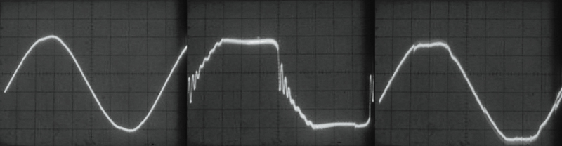
wwaveform_no-load.jpg

Inherent Voltage waveform Grid Power w/ no load (Left). Conventional AVR Power w/ no load (Center). Inverter Power w/ no load (Right.)

But that is not the only benefit to using a magnetic ballast over a non-PFC electronic ballasts on a portable generator. If you don’t have access to the newest PFC electronic ballasts, the older magnetic ballasts are in fact cleaner running on portable gas generators than non-PFC electronic ballasts. As mentioned above the harmonic distortion created by non-PFC ballasts reacting poorly with the distorted power waveform of conventional AVR generators limited the number of HMIs you could power on a portable generator. The primary factors limiting the use of HMIs on portable generators has been the inefficient use of power by non-PFC electronic ballasts and the harmonic noise they throw back into the power stream. The adverse effects of this harmonic noise (evident in the oscilloscope shots below), can take the form of overheating and failing equipment, efficiency losses, circuit breaker trips, excessive current on the neutral wire, and instability of the generator’s voltage and frequency. For these reasons it has never been possible to operate more than a couple of 1200W HMIs on a conventional 6500W portable gas generator.


wwaveform_elec_ballast.jpg

Voltage waveform distortion caused by 1200W non-PFC electronic ballast operating on grid power (left), on power generated by a conventional AVR generator (middle), and power generated by an inverter generator (right)

As is evident in the oscilloscope shots below of a 1200W magnetic HMI ballasts, the lagging power factor caused by the inductive reactance of magnetic ballasts has by comparison only a moderately adverse effect on the power waveform. Outside of causing a voltage spike in the inverter power, magnetic ballasts actually show a positive effect on the already distorted power waveform of the Honda EX5500 conventional generator. For this reason magnetic ballasts work better on conventional generators with frequency governors than do non-PFC electronic square wave HMI ballasts.

wwaveform_mag_ballast.jpg

Voltage waveform distortion caused by 1200W magnetic ballast operating on grid power (left), on power generated by a conventional AVR generator (middle), and power generated by an inverter generator (right)

These oscilloscope shots show that if you don’t have access to the newest PFC electronic ballasts, the older magnetic ballasts are in fact cleaner running on portable gas generators than non-PFC electronic ballasts. And, where inverter generators do not require crystal governors to run at precisely 60Hz, you can operate magnetic HMI ballasts reliably on them.

Of course there are downsides to using magnetic ballasts. One down side is that you are restricted to using only the safe frame rates and shutter angles. But, when you consider that every film made up to the early 1990s were made with magnetic HMI ballasts you can see that being limited to the safe frame rates is not all that restrictive. Another downside to magnetic ballasts is that you can’t load the generator to full capacity because you must, as Slondon mentions above, leave “head room” for their higher front end striking load. When choosing HMIs to run off portable generators, bear in mind that magnetic ballasts draw more current during the striking phase and then they “settle down” and require less power to maintain the HMI Arc. By contrast, an electronic ballasts “ramps up”. That is, its’ current draw gradually builds until it “tops off.”

While older HMIs with magnetic ballasts are less expensive to purchase or rent, Power Factor Correction (PFC) makes the newest electronic ballasts worth the extra money when it comes to lighting with portable generators. As discussed in my previous post, the substantial reduction in line noise that results from using power factor corrected ballasts on the nearly pure power waveform of an inverter generator creates a new math when it comes to calculating the load you can put on a generator.

- Guy Holt, Gaffer, ScreenLight & Grip, Lighting and Grip Rental & Sales in Boston
 
I'm guessing there's multiple reason why you run that one 220 line from the genny to your step down transformer...just correct me if I'm wrong. First because if you have one 60 amp 220 line that will give you two 60amp 120 lines once you run it through your transformer. Then you also don't have so much line loss when you run a 220 line instead of 120, correct? I've heard about people talking about how they run power lines at much higher voltage since they have to do such long runs, but why is it that with this higher voltage you can do a longer run? Is it just because that voltage drop is the same no matter what voltage you're running at? And 1 volt for 220 is a lot less than 1 volt for 120?

Is there a way to calculate line loss over a given run with a given voltage?

This is a good question – unfortunately there is no simple answer - so please bear with me. First, utility companies transmit power at high voltage to reduce the size of transmission lines. According to Ohm’s Law (Watts = Voltage x Amperage) the higher the voltage (V), the lower the current (Amps) required to perform the same work (Watts). By transmitting at a high voltage, the utility companies substantially reduce the amount of current that will be drawn over the lines which allows them to use smaller gauge cable. When you are running thousands of miles of utility lines, the savings in copper is substantial. Utility companies step down the high voltage power that they transmit to 120V with transformers on the utility pole.

How using transformers on portable gas generators reduce line loss has nothing to do with using smaller cable, but with running a smaller load on larger cable. To understand how transformers reduce line loss in this situation, you must first understand that a 240V circuit of a portable generator is actually two 120V circuits.

gen_wiring_sch.jpg


Wiring schematic of an AVR portable generator

As you can see from the wiring schematic of a portable generator above, if you measure the voltage from each hot pin of the generator’s 240V 4-pin receptacle to ground it will be 120 volts, and if you measure the voltage between the two hot pins of the 4-pin receptacle you will notice that it is 240 volts. As illustrated below, the 120 volts of the two poles of the generator’s alternator add up to 240V because the 120V circuits are on opposing legs of a single phase circuit and 180 degrees out of phase with each other.

Voltage_Adds_to_240-Volts.jpg


The voltage of opposing legs of a single phase circuit add while the current carried on the legs subtract.

Now if you feed the 240 Volt output of the generator to the primary side of a transformer, on the secondary or load side of the transformer it will be converted to 120 Volts in a single circuit that is the sum of the two single phase legs (as illustrated below.) And, as you can see by the wiring diagram above, since the 240V output comes directly from the generator windings, by-passing the breakered branch circuits of the generator power output panel, the transformer gives you the full capacity of the generator in a single large 120V circuit (60A circuit in the case of the enhanced 7500W output of our modified Honda EU6500is generator.)

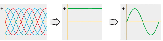
Things get quite a bit more complicated with inverter generators. Unlike the simple two-pole alternator of the AVR generator in the wiring schematic above, an inverter generator uses a core that consists of multiple stator coils and multiple rotor magnets. Each full rotation of the engine produces more than 300 three phase ac sine waves at frequencies up to 20 kHz, which is considerably more electrical energy per engine revolution than produced in conventional two pole AVR generators. A fixed diode bridge rectifier then converts the more than 300 three phase ac sine waves to a DC voltage (about 200 V). Single phase AC Output is then generated from the high voltage DC by a inverter module with voltage and frequency set by micro-processor controlled switches using a PWM control logic.

Inverter_Power_Flow.jpeg


The three phases of the inverter generator process: high frequency AC converted to DC; DC inverted to stable clean 120V, 60 Hz AC.

Because of the addition of the inverter unit, there is not a direct circuit to the alternator windings as there is in the AVR generator depicted above (not that we could use the high frequency 3-phase power anyway), but the principle is the same. A transformer will step-down the 240V output of an Inverter, just as well as that of a two pole alternator, the wiring just gets a little more complicated on the generator side.

One benefit to using step-down transformers on portable generators is that they enable you to power larger lights on the generator than you could otherwise. As illustrated below a step-down transformer not only accesses more power through a higher rated circuit (the 30A/240V Twistlock), but it also splits the load of whatever you plug into it evenly over the two legs of the 240V single phase circuit of the generator. For example, if you plug the 42A load of a 5k into the secondary side of the transformer, the transformer splits the 42A load evenly between the two 120V circuits (21A each) making up the generator’s single phase 250V circuit. This characteristic of transformers is important to understanding how they mitigate line loss.

Gen_Transformer_Schematic.jpg


Wiring of a portable generator w/ 240V-to-120V Step-down Transformer

To help us understand how this reduces line loss, let’s take as a practical example the use of the same non-Power Factor Corrected (PFC) Arri 1200 Electronic Ballast mentioned above on a portable generator to light the deep background of a night scene. So that we do not pick up generator noise on our audio tracks, we will likely have to move the generator, even the super quiet Honda Inverter generators, around the corner of a building or operate it out of our grip truck. In order to do so will require running, let’s say 200’ of cable from the generator to where the camera is on set. However, it is likely that we will have to run another 100’ of cable from the camera position to the light if it is lighting the deep background of our shot. What kind of line loss will we have over a 300’ cable run and will it be acceptable?

To calculate the voltage drop (Vd) over the 300’ cable run you would use the following equation:

Voltage_Drop_Equation.jpg

According to this equation we need to know the following factors in order to calculate the voltage drop (Vd) our non-PFC 1200W electronic ballast will cause over a 300’ cable run:

Cm: The cross-sectional area of a wire measured in circular mils (cmil). For the sake of this discussion let’s assume we are running regular Hardware Store style 14/3 extension cables which have a cross-sectional area of 4107 cmils.

L: The length of the wire in feet. This is the one-way distance from the source to load. Note that in the equation, this number is multiplied by 2 to get the two-way distance the current has to flow to complete the circuit. In our example we would then enter 300’.

I: The current carried by the cable. According to the manufacturer’s website, the non-PFC Arri 1200W electronic ballast has an Apparent Power of 2290VA which means that it will draw roughly 19 amps at 120V (2290VA /120V = 19.08A.)

K: The specific resistance of the material making up the conductor. Since we are using copper cable, K would be 10.8 at 25 degrees C.

As you can see, the math is getting pretty complicated. Since there are Line Loss Calculators for this kind of thing available online (at www.stealth316.com/2-wire-resistance.htm ), let’s use one of those instead.

If we enter the parameters for our example into the calculator (distance of 300’, load of 19A) we get the results in the table below, or a line loss of nearly 15 Volts (14.781) when powering a non-PFC 1200W electronic ballast on 300’ of 14 Awg cable. Where the allowable voltage drop according to the National Electrical Code (NEC) is 6V at 120V line level, our drop is more than double the allowable amount. If we look at the effect of this voltage drop on the ballast, we see why it is not allowable by the NEC.

VoltageDrop_19A300ft.jpg


Voltage Drop of 19A Load over 300ft


Since the non-PFC Arri 1200 Electronic Ballast we are using is a “Constant Power” electronic ballast it will draw more current to compensate for the drop in voltage to maintain the ballast’s Apparent Power of 2290VA. At 105V it will then draw 21.81A amps (2290VA/105V = 21.81A.) Since the Arri Ballast has an operating range from 90-125V, it is not likely that the ballast will shut off from under voltage, but it is very likely that the 20A breaker providing over current protection to the generator’s Edison U-Ground receptacles will trip and shut the light off. Where I am out of space, I will pick up with what happens when we power the same light on the 30A/240V single phase circuit of the generator through a step-down transformer instead.

Guy Holt, Gaffer, SceenLight & Grip, Lighting and Grip Rental & Sales in Boston
 
Where I am out of space, I will pick up with what happens when we power the same light on the 30A/240V single phase circuit of the generator through a step-down transformer instead.

Line loss in a distro system should be eliminated where ever possible because its’ accumulative effect can be dramatic. In this case it causes the non-PFC 1200W HMI ballast to draw an excessive amount of current, which trips the breaker on the generator, throwing the entire set into darkness. In the case of tungsten lights, the effect of line loss is less dramatic, but should be avoided all the same, because the output of tungsten lights fall off geometrically as voltage decreases. For example a 1k lamp operating at 90% rated voltage (108V) produces about 68% of its normal light output - your 1kw lamp is now a 650W lamp. But, that is not all, as the light intensity decreases, so does the color temperature (Kelvin) of the emitted light. In the case of generator output, voltage loss translates into an exponential loss in power. That is because, if you double the ampere load on the cable, the voltage drop also doubles, but the power loss increases fourfold. What this means is that when a distribution system has a large voltage drop, the performance of the generator (its maximum effective load) is reduced.

HD_PP_Demo_Transformer-Distro.jpg


A Distro System consisting of a 60A Full Power Transformer/Distro, 2-60A GPC (Bates) Splitters, 2-60A Woodhead Box distributes power from a modified Honda EU6500is. Even though the generator is 100' away to reduce noise, plug-in points remain conveniently close to set.

For example, an overall voltage drop in a generator/distro system of 25 Volts will cause a non-PFC 1200W electronic ballast to draw 4 more Amps than it would otherwise (very possible when you take into account not only voltage drop as a result of line loss, but also to overheating distro equipment and load on the generator – use this link for details.) Four Amps is a considerable loss in the capacity of a generator when you consider that a Kino Flo Parabeam 400 only draws 2 Amps. If we are able to eliminate the voltage drop in our example we would be able to operate two more Kino Parabeam 400s on our generator - that would be an appreciable increase in production capability. For these, and other reasons as well, it is important to eliminate voltage drop wherever you can.

HD_PP_Demo_Distro.jpg


60A GPC (Bates) Splitters and Woodhead Box.

To understand how using a transformer with a portable generator can greatly reduce line loss, let’s look at what happens when we power the same light on the 30A/240V single phase circuit of the generator through a step-down transformer. Instead of running 14/3 Extension cords to the camera position on set, we run 200’ of heavier gauge 250V 10/3 Twist-lock feeder cable from the generator to a step-down transformer next to the camera on set. From the transformer, we run another 100’ of 120V 6/3 Bates extension cable from the camera position to the light. What kind of line loss can we now expect over our 300’ cable run and will it be acceptable?


HD_PP_Demo_P2L.jpg


60A Woodhead Box running Power-to-Light PFC 800W ballast (left) and PFC 1200W ballast (right.)

Let’s calculate the line loss on the first leg of our cable run first. Since, the transformer automatically splits the load of what ever is plugged into it evenly over the single phase circuit of its primary side, we are now running 9.5 amps on each cable conductor instead of the 19A we ran before. And, we are running our smaller 9.5A load on a larger conductor (10 Awg cable instead the 14 Awg cable before.) If we enter these new parameters for our example into the line loss calculator we get the results in the table below, or a line loss of only 1.93 Volts when powering a 1200W HMI on 200’ of 10 Awg cable. Where this is the line loss on just one of the two 10 Awg conductors of the 240V circuit, is this our effective voltage drop? Yes and no.

VoltageDrop_9.5A200ft.jpg


Voltage Drop of 9.5A Load over 200ft

No, in the sense that it is only the line loss on each conductor of a single phase circuit feeding the primary side of our step down transformer. The voltage drop we experience in a practical sense is what we get on the secondary side of the transformer where we would plug in our light. To calculate that, we simply divide the 236.14V being fed to the transformer after losing 1.93V to line loss on each of its two conductors (240V - [2 x 1.93V] = 236.14V) by 2 (the 2:1 step-down ratio of the transformer.) What we get is a voltage output of 118.07V on the transformer secondary, or an effective voltage drop of 1.93V. So, yes, 1.93V is our effective line loss thus far. What accounts for the appreciably less line loss? The line loss is appreciably less in this case because 1) the resistance of a conductor decreases in proportion to its cross-sectional area (we are now using a larger conductor), and 2) voltage drop varies with the load. The smaller the amperage load, the smaller the line loss (we have cut the load on each conductor in half by using a transformer to step-down from 240V to 120V.)


VoltageDrop_19A100ft.jpg


Voltage Drop of 19A Load over 100ft

To the 1.93 Volt drop from our 200’ 10/3 Twist-Lock feeder cable run, we need to add the line loss we will have on the 100’ run of 120V 6/3 Bates extension cable. If we enter these new parameters for our example into the line loss calculator we get the results in the table above, or a line loss of only .76 Volts when powering a 1200W HMI on 100’ of 6 Awg cable. The total line loss when using a transformer/distro system then comes to only 2.69 Volts which is well within the 5% acceptable voltage drop mandated by the NEC, and 589% less than what we experienced running 300 ft of Hardware Store style 14/3 extension cords from the generator to the light.

To compensate for even this slight line loss, as well as the voltage drop we can expect on the generator from running it near full load, you can use a transformer that will boost voltage slightly. Boost transformers provide variable taps on the primary side that enable you to adjust the step down ratio to boost their output above the standard 2:1 ratio. This boost capacity of transformers can be used to compensate for accumulative voltage drop and assure full line level (120V) on set. For example, our standard Transformer/Distro is designed to boost the voltage on the load side (secondary) of the transformer by 5 percent. For instance, if you were to plug the Transformer/Distro directly into a generator running with no load and feed the supply side (primary) of the transformer with the generator's 240V output, you will get 126 Volts out on the secondary side where you would plug in lights. We have designed this slight boost into our standard Transformer/Distro to compensate for the slight line loss that is unavoidable over a long cable run, and the voltage drop on the generator under load. For instance, if we fed our standard Transformer/Distro the 236.14 volts we would have 200' away from a generator operating the 1200W non-PFC HMI in our example above (240V from the generator – 3.86V line loss to cable – 5V drop on generator from the load), 121.47 volts would come out on the secondary side where you plug in (115.57V Output of a straight 2:1 step-down ratio + 5.90V boost of 5% boost to primary voltage after step-down.) This example shows how the slight boost we build into our standard Transformer/Distros, not only enables you to place the generator further from set where you won't hear it, but also assures that the supply voltage on the secondary side of the transformer does not drop too low. By comparison, without the line-loss compensation of our Transformer/Distros, to avoid the severe voltage drop in our example above you would have to keep the generator close to set where it would be heard on the audio tracks.

For more detailed information on line loss, I would suggest you read an article I wrote on the use of portable generators in motion picture production. The article is available at www.screenlightandgrip.com/html/emailnewsletter_generators.html.

Guy Holt, Gaffer, SceenLight & Grip, Lighting and Grip Rental & Sales in Boston
 
Awesome. Thanks for the explanation! I feel like I have a bit better understand of how this all works.
 
Back
Top