Electrical Question About Safe Wiring!

OldCorpse

Rockin the Boat
I am NOT an electrician. I only know extremely basic stuff like hot, neutral, ground and serial vs parallel circuits. I want to build a light I need for an idea I have. Basically I want to have a 12 bulb light (each bulb 85W). I want each bulb to have its own on/off switch. The complication is that I can't really connect all 12 in a parallel circuit, because all the pigtails would not fit in (they'd be sitting along a thin PVC pipe inside of which would go all the wires). So my idea was to run all the individual 12 hot wires (with an individual switch on each wire) to some kind of a bus bar like this and attach them to the screws (there are only 10, but I would double up on a couple of them to get 12 points of contact), and then attach a regular 12 gauge wire to the big screw that would go to the 110V 15A AC. Then I would do exactly the same thing with the 12 neutral wires (except of course they would have no switches on them) on another separate bus bar that also terminates in a 12 gauge wire (neutral) going to the AC. Of course, I'd make sure that the two bus bars are absolutely isolated from each other and not in any contact with each other! My question - is there any reason why this would not work?

Question #2, but this is a long-shot, is there some kind of breakaway distributor/connector in two pieces, where I could run the 12 hot wires and the 12 neutral wires through it, and be able to simply disconnect the two parts physically and then connect them by plugging into each other - and hopefully it would not be huge - not bigger than maybe 2-3 inches diameter.

Thank you!
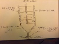
 
#1 - It's not exactly clear what you are doing, but it sounds ok. Post a sketch.

#2 - You want two, 1 amp x12 pin connectors?
 
Last edited:
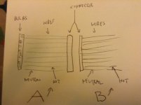
I have zero skills drawing, so apologies for how crude this is, but regarding

#1) the bus bars would be two like the ones I linked to on Amazon

#2) connector sketch - idea being that it's like a breakaway cable - I can connect and disconnect very easily, and it'll always connect/disconnect the same 12 hot and 12 neutral wires.IMG_1778.jpgIMG_1779.jpg
 
Yes, you can do this. It's not clear to me what UL/CSA would require, if anything regarding short circuit safety. I've never really understood UL/CSA requirements for light fixtures. I'll do some reading. But your project is exactly the same as say, a chandelier with many bulbs. A main cord comes to the fixture and then the wires are distributed to the individual bulbs. The rating of the wire only needs to be as big as required for the current expected to flow through it.

Regarding the breakaway, yes, there is likely to be 24 pin connectors with a 120v/1amp rating that could be used for this.
 
Thank you, Paul. There are still a couple of things I'm not 100% sure about. Is there anything I need to do wrt. ground? The 12 bulb sockets are going to be attached individually to a PVC pipe. Wrt. to the breakaway, "a connector with 120v/1amp rating"... well, each bulb is 85W, so I guess the wire for each individual bulb need only be rated at 1amp, but if there are 12 bulbs, the total power draw (of all 12) is 12 x 85W = 1020W, so divided by 100V = ~10.2 amps... right? So the total power the connector must be able to handle is at least 10.2 amp (or 15 amp to give us margin) - no?
 
Regarding ground - you don't need to do anything except attach ground to any exposed metal. Since you have it in PVC, this is not an issue. The point of the ground wire is to have all exposed metal surfaces grounded to assure that if a wire came loose inside, if it touched the exposed metal, it would trip the breaker rather than have the metal become electrified. Since you don't have any exposed metal, you don't need the ground.

Regarding the connector, what you said is correct. But typically, connectors are not rated that way. They are rated on a per-pin basis.
 
Aah, thank you, Paul, that makes this much more clear, and makes sense to rate the connector on a per-pin basis. I think I'm going to carefully move forward. My first task is going to be to find the correct materials. The bus bars - I'm thinking of using the ones I linked to on Amazon. Individual sockets, porcelain, rated for 660W 250V each, like this one, should be able to handle a 85W CFL spiral bulb, for switches something like this rated for 20A 125VAC, 14 gauge wires for the sockets and 12 gauge wires going to the AC. For a connector, I really have no idea... I do see something like this, but have no clue as to whether it's appropriate - so that remains a big question.
 
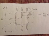
The reason I need a connector is for breakdown/storage convenience of the light. See sketch:

IMG_1781.jpg

Now, a 1" PVC pipe (not pictured) is going to go into the center of this square at 90 degrees, and all the wires are going to go from the bulbs through the 1/2" PVC pipes and support struts in the square and into that 1" PVC pipe that is going to be about 4' long (and through that 1" square I'd thread the wires for the AC. If the 4' long 1" PVC pipe were to be permanently attached to the square with the lights, it would be quite space consuming to store. Far better, if there was an easy way to detach the square from the long pipe for storage, and be able to connect and disconnect them quickly. That's where the connector comes in.

The reason I need a 24 pin connector is that I want to have 12 on/off switches on all the individual hot wires from each bulb, and I want that to be at the other end of the 4' long PVC pipe, so I need to have the connector step in and connect/disconnect the 12 hot and 12 neutral wires before, so that I can have 24 wires going in, and the same 24 wires going out.
 
Ok, got it now. You don't need 24 pins. You need 13. One for each hot and one neutral. The neutrals don't need to be switched. Just connect all the bulbs neutrals together and switch the hot on/off. But then you need the neutral to be able to handle the total current.
 
Hey Paul, yes you are right - after all, the on/off switches are only on the hot wires... duh! So, basically, I can put the *neutral* bus bar ahead of the connector and then lead off the bar into the connector with one wire for the neutral - and given that the light will draw 10-11amps, I think a 12AWG or even a 14AWG wire should do it. So yes, I'd need a 13 pin connector rated at at least 15amps (for safety).
 
Or use a terminal strip to break out the wiring. A standard 15 amp edison connector will work for your feed.
 
Or use a terminal strip to break out the wiring. A standard 15 amp edison connector will work for your feed.

OK, I have no idea what that means, sorry :(

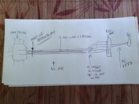
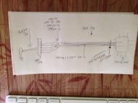
In any case, I want to clear up what I need. A 4' long pipe. At one end "A" is the light fixture. At the other end of the 4' long PVC pipe, "B", are the 12 on/off switches. I need to break away at point "A", not at point "B" - in other words, I need to break away the 12 hot wires (plus the one connected neutral wire), because of the switch position. Illustration:

IMG_1785.jpg

In other words, because of where the on/off switches are going to be positioned - to control each individual light - the breakaway point must be before it reaches the switches, so I need to breakaway all 12 hot wires and the one cumulative neutral wire.
 

Attachments

  • IMG_1786.jpg
    IMG_1786.jpg
    70.1 KB · Views: 0
Last edited:
"Common" neutral is the correct term in this case.

I wouldn't use porcelain sockets like the ones you posted in that link (to my knowledge, all medium base lamp holders have the same 660w / 250v ratings). There are other styles that would better suit your needs as far as mounting them on a piece of PVC pipe goes.
 
Thanks, Moseph, I am completely open to any suggestions wrt. this project. The PVC pipe that these sockets would be attached to - the light fixture square - would be 0.5" diameter, and the inside struts would also be 0.5" PVC. That's not a very big pipe. I'm definitely not excluding other sockets. I'm also thinking that I may need to carefully consider how exactly to attach the sockets - I may need to affix some kind of additional support base between the pipe and the socket. Obviously, my aim is to make sure that one can screw in the bulbs securely and not have any of the sockets jiggle or otherwise turn or anything - my aim is to make them rock solid. Two complications: I cannot have the resulting fixture be too heavy - the lighter the better - and not too big - the smaller/thinner, the better... reason being is that this light would go inside a large brolly - the Impact 7' Parabolic Umbrella (Silver) with diffuser. So basically the brolly is like a large softbox - therefore the fixture inside cannot be too heavy or large (the bigger the non-light elements, the more light they are obstructing). That is one reason why I'm going with a thinner 0.5" pipe. The pipe leading out of the brolly (along which will be the shaft of the umbrella) is beefier at 1" diameter. In any case, if you can think of some other socket, I'm all ears - I would be using 85W spiral CFL bulbs (12 of them), which are approx 4" wide and 11" long, standard socket size base 26/27. Thanks!
 
Do you already own the umbrella? It claims to be parabolic. Not sure how parabolic it actually is, but if it's pretty dead on, this whole contraption you have in mind would seem a bit misguided. Parabolic reflectors work by having a tiny source of light placed right in the focus so that all the rays get reflected out parallel to each other. I would invert the whole thing so that the lamps are pointed inwards rather than out, so they're closer to that focus, and I would probably reduce the number of lamps too.

I also wouldn't use PVC for anything structural unless you need to be able to disassemble it. Any kind of fixture involving a bunch of medium base sockets like bay lights, strip lights, or covered wagons, typically use 1x3 batten to mount the sockets with wood gussets at any corners to hold it together. They'll use sockets like these - https://www.1000bulbs.com/product/5...BaseShopping&gclid=CN70x9_S5cMCFdgVgQodgwoAPg - mounted with drywall screws, and THHN wire with crimp-on spades to connect everything together. If necessary, the wire is gets stapled down to the wood too.
 
Thank you, Moseph, that's definitely food for thought. How parabolic is it... hard to say, on B&H website they say "You can also vary the light-to-umbrella distance along the shaft for a harder or softer light. This silver version is ideal for throwing the light over a long distance", implying that indeed, it is parabolic since it can throw the light a long distance (the light rays are more parallel). And of course, a smaller source is going to be a harder light, so inverting the bulbs to point inward will concentrate and make the light source smaller. Hmm. I may need to re-think the design of this. THANK YOU FOR YOUR VALUABLE THOUGHTS!!!"
 
1) Then neutral is NOT switched. You can "daisy-chain" it from one socket to the next.
I would probably use TWO neutral wires, one for each half of the gadget.
2) 85W @ 120V is less than 1 amp. So you don't need huge wire (or connectors) for the hot feed to each lamp for such a modest load.
However, the neutral line will take the whole 1020 watts which is 8.5 amps, so wiring and connector rated at 10A would be minimum for the neutral.
3) I would recommend making this out of "thinwall" rigid electrical conduit (vs. PVC pipe). AND connecting the metal to the green-wire safety ground.

With such a broad source, it is not clear why you need a focusing reflector behind them.
In fact, a focusing reflector requires a centralized source in the center (at the focal point).
Your ring design has NO light at all coming from the center. So it seems unlikely that combination will be very effective.
 
Last edited:
I don't quite see why this is so complicated - most lamp holder terminals are sized to take two conductors, so supply in one side, then loop out to the supply of the next and so on? In your home, you'll have ceiling lights wired exactly like this. In the UK, with our higher voltage, we use 1.5mm2 cable for lighting circuits, unless we're doing something VERY bright, and then we'd update to 2.5mm2. In fact, for lower Wattages, 1mm2 cable could be quite OK. I can't speak as to US code, but open terminal blocks that are not finger touch proof wouldn't be acceptable unless a tool was required to open the unit up.
 
Maybe I missed this but what are your buss bars going to be contained in? Were you going to put over current protection on the line side of the bus bars? That would be extremely recommended to protect everything down stream of the input connector.
 
Back
Top