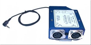
Denecke PS-2

yoclay

Veteran
I just recently purchased a Sony PCM-D50 and want to use a Denecke PS-2 XLR adapter with it. What is not clear to me is the cabling situation of this unit on the back end (the opposite side of the XLR's). Out of the hundreds of photos out there of this unit absolutely none shows another angle and explains the output cable. I have heard that it does not actually have an 1/8" minijack output and that this is in fact a modification which used to be done by Sound Professionals. So what are people doing to actually use this with their recorders?

Photos and specifics in terms of cables would be appreciated.
Lastly if anyone has one of these kicking around that they are no longer using and would like me to take it off their hands....
 
Searching Google for Denecke PS-2 and clicking the "Images" option returns 5890 pictures.
The third one shows an excellent view of the back-side: http://imageshack.us/photo/my-images/154/ps2vs3wire3vu2.jpg
It appears to have a captive output cable.

Furthermore there are some excellent shots of the insides of the Denecke PS-2 showing the output cable that appears to be two pair inside a shield.
http://taperssection.com/index.php?topic=56913.0

It should be possible to put 3.5mm output connector(s) on this cable. Although the cable is rather on the large side for 3.5mm connectors and probably won't be easy.
 
"captive output cable"

Not sure what that means specifically, could be many different things.

I still have never seen the plug which terminates this cable. Aside from a modded one by Sound Professional.

Are you suggesting I can just add a 3.5mm connector at the end of this cable and I am good to go?

Personally, I am not so sure of that...
 
Last edited:
Did you look at the pictures? Captive means that the cable is hard-wired to the Denecke box with no connector.
I agree that Denecke's documentation seems to assume that you know the output is a pair of male XLR connectors. It never states it explicitly.

The SoundProfessionals mod appears to simple remove the stock captive output cable and replace it with a common 3.5mm stereo cord assembly.
Other than figuring out the pinout (which should take 5 minutes with a meter), it seems like a 5-minute soldering job. It's not rocket surgery.
I will do the mod for you for $20 plus shipping. Or you should be able to find somebody in your circle of acquaintances who is handy with a soldering iron.

DEN-PS2-MINI.jpg
 
Found this regarding the 1/8" mod:

http://taperssection.com/index.php?topic=128573.0

It depends entirely on what microphones you're using. There are standards for connecting balanced microphones to balanced inputs and standards for connecting unbalanced microphones to unbalanced inputs, but no standards for connecting balanced microphones to unbalanced inputs.

Someone else may come along next and post one simple connection scheme and swear that it's generally OK. But any such answer (e.g. "take the hot lead from pin X, and ground pin Y to pin Z") will work for some microphones while causing others to distort unnecessarily (i.e. run out of headroom 6 dB or more below the usual level), and will cause still others to give no usable signal at all. That's just the way it is. Any particular adapter or wriring scheme will only work for some types of microphones and not others.

You can use input transformers to turn your unbalanced inputs into balanced inputs. But good input transformers aren't small and they aren't cheap. To make a connection that can work without them, you have to know how the output circuit of your particular type of microphone works. Sometimes the owner's manual will show a wiring diagram for connection to unbalanced inputs. But even different microphones from the same manufacturer may require a different wiring scheme. So the best advice would be that if it's not in the manual, ask the manufacturer.

I am using an MKH-60 and occasionally an Oktava MK012 (hypercardioid).

Later someone replied:

on the PCB of the PS2, the wiring output is as follows:

RIGHT CHANNEL
red wire +
clear wire -
shield is the ground

LEFT CHAN
blue wire +
black wire -
ground.

they are laid out across the edge of the PCB, and are very easy to get at for de-soldering off of the board.
the stock cable they use is a bit too thick for 3.5mm plugs, only the switchcraft fatty will really fit it well. I've just removed the cable entirely and replaced it w/a run of millspec. two hot conductors for L/R and the shield for ground.

the output, as we know is balanced. this re-wireing is a ghetto-unbalanced version, but it works just fine and has absolutely no issues or interference with whatever mics you are using. the input scheme remains unchanged. It allows you to run condensers into a small deck like an r9 or the new sony...

Think I would definitely be interested in taking you up on your offer Richard.
Guess I am not a rocket scientist.
 
Back
Top