dBFS, dBu, "nominal" levels ... huh?

Seriously? Do you really think you're hearing a 10 khz square wave?

What sort of gain section, let alone transducer, is delivering an audible 10 khz square wave?

Fran

BTW no I don't think I can hear a TRUE 10K square wave. BUT a 10K square wave sounds significantly different than a 10K sinewave. It is certainly softened by the physical limitations of speakers and my ears. So I am hearing something "sharper" than a sige wave and softer than a square wave.

You seem stuck in a smash up of various things you have read. Perfect means what comes in is EXACTLY what goes out. Analog to digital to analog is not perfect. Claiming it is shows a large lack of knowledge about what is going on. Claiming it is "perfect" because you can't hear the difference is just silly.

MAYBE 44.1/16 is "good enough" for you and if so go for it. For most people 44.1/ 24 (or 48 if you are working in film) is noticeably better, and for some 96/ 24 is noticeably better.

But you were arguing perfection and none of the above are perfect. This started because you accused someone of explaining digital incorrectly and proceed to do an even more inaccurate explanation. The first explanation was simplified but basically correct, yours not so much. Since then you have kind of fallen back on "well you can't hear the difference", which is kind of true but doesn't make your claim of perfection any more valid.

Normally I would just let it go because it won't make much difference to you. But this is the kind of thing some newcomer is going to see and incorporate in their "knowledge base" and will just add more confusion down the line.

But I think I have explained the holes in your arguments and by now folks will at least feel the need for looking further. So as I said I'm moving on and the last word is yours.
 
BTW no I don't think I can hear a TRUE 10K square wave.

Last time I was near a NTSC TV I still could here the 14KHz squeal from the horizontal scan frequency. I still regularly hear circuits that are powering 9600 baud serial lines (who uses such 'low' tech... but I digress...).

And definitely can here over compressed MP3 squealing.
 
Last time I was near a NTSC TV I still could here the 14KHz squeal from the horizontal scan frequency. I still regularly hear circuits that are powering 9600 baud serial lines (who uses such 'low' tech... but I digress...).

And definitely can here over compressed MP3 squealing.

My point and I think his is that since you can only hear a fraction of the harmonics so you are not hearing an "actual" square wave, but a distorted sine wave.

Though there is some research that points to people being able to "perceive" sounds that are physically to high for them to actually "hear" so that may also figure in.
 
There was a rather detailed discussion on this and other audio science issues over on the JW Audio group http://jwsoundgroup.net a few months back which may be of interest. However I don't have a direct link or the time to search at present.
Maybe this one http://jwsoundgroup.net/index.php?/topic/20548-sampling-rates/ ?


What sort of gain section, let alone transducer, is delivering an audible 10 khz square wave?
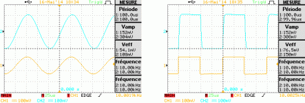
I agree for the "transducer" thing. But the "gain section" part is not really clear to me. I probably don't understand what you are tying to say. Sorry about that. But this gave me the idea to check how my low-end mic preamp behave when fed with a 10kHz square wave. I was wondering if some kind of filtering inside the device would alter the signal while traveling from the Mic input to the Line output. Back to scope again:

10000Hz-square-gain.gif

Beside the gain, there's not much difference between the input (1) and output (2) signal. We could just barely notice an increased rise/fall time.


It is some capacitors and resisters that are smoothing out the digital steps. It's not a reconstruction at all, it has no idea what the original looked like and all it is doing is averaging the levels between samples.
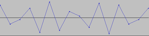
I thought myself that the D/A was mostly "connecting the sample points" together. And from what I can tell on other application domains, that's what the usually do, with more or less "smoothness" between the samples. So, I assume there is here some kind of output stage at work, as, believe it or no, the following wave form, when played, produce the output signal bellow:

sin-12000Hz-sampled-44100.gif
A0034DS.GIF

The samples are an extract from a recording at 16bits/44.1kHz of a sine wave at 20kHz [SUB](don't pay too much attention to the scope frequency indicators. The signal duration is too short to display accurate results)[/SUB].

Please note how the "middle" sine is perfect, of same amplitude as the others. Whereas, by looking at the sample points, one might have expected a much worst reconstruction ?!? This is kind of puzzling me...
 
Last edited:
BTW no I don't think I can hear a TRUE 10K square wave. BUT a 10K square wave sounds significantly different than a 10K sinewave. It is certainly softened by the physical limitations of speakers and my ears. So I am hearing something "sharper" than a sige wave and softer than a square wave.

You seem stuck in a smash up of various things you have read. Perfect means what comes in is EXACTLY what goes out. Analog to digital to analog is not perfect. Claiming it is shows a large lack of knowledge about what is going on. Claiming it is "perfect" because you can't hear the difference is just silly.

MAYBE 44.1/16 is "good enough" for you and if so go for it. For most people 44.1/ 24 (or 48 if you are working in film) is noticeably better, and for some 96/ 24 is noticeably better.

But you were arguing perfection and none of the above are perfect. This started because you accused someone of explaining digital incorrectly and proceed to do an even more inaccurate explanation. The first explanation was simplified but basically correct, yours not so much. Since then you have kind of fallen back on "well you can't hear the difference", which is kind of true but doesn't make your claim of perfection any more valid.

Normally I would just let it go because it won't make much difference to you. But this is the kind of thing some newcomer is going to see and incorporate in their "knowledge base" and will just add more confusion down the line.

But I think I have explained the holes in your arguments and by now folks will at least feel the need for looking further. So as I said I'm moving on and the last word is yours.

I apologize for causing so much frustration. As you've said, we're quite likely saying the same thing past each other.

My concern is the same as yours - leaving good information behind for those that follow. I think that if we were speaking face to face we might find points of agreement by tuning our definitions a bit.

As it is, thanks for all your input.

Fran
 
Maybe this one http://jwsoundgroup.net/index.php?/topic/20548-sampling-rates/ ?


I agree for the "transducer" thing. But the "gain section" part is not really clear to me. I probably don't understand what you are tying to say. ...

Definitely my bad. Modern gain sections and even power sections can do amazing things and as you demonstrate, pass a pretty decent square wave.

Transducers not so much. Not to mention ears. Thanks for your input.

Fran
 
My point and I think his is that since you can only hear a fraction of the harmonics so you are not hearing an "actual" square wave, but a distorted sine wave.

Though there is some research that points to people being able to "perceive" sounds that are physically to high for them to actually "hear" so that may also figure in.

Well, sure, and various compression techniques for both audio and visual information take advantage of what humans perceive, or don't, and reduces the amount of data correspondingly.

There's also an issue with transient response, which if the signal is not given sufficient bandwidth, distortion occurs, which depending is perceived by the human listener.
 
Please note how the "middle" sine is perfect, of same amplitude as the others. Whereas, by looking at the sample points, one might have expected a much worst reconstruction ?!? This is kind of puzzling me...
Answering to my own interrogation (per http://xiph.org/video/vid2.shtml -- at 6:50):

"There is only one band limited signal that pass by all the sample points."
​


Of course, there is an infinite number of signals that could be drawn to connect the samples. But only one of them containing only of harmonics below the Nyquist frequency. That uniqueness, if I understand it well, is the exact purpose of the Nyquist Shannon theorem.


BTW, the Xiph.org video above is really great! If you read this thread, you probably should watch it as it clarifies many things about the "sampling theory"...
 
Last edited:
I thought myself that the D/A was mostly "connecting the sample points" together. And from what I can tell on other application domains, that's what the usually do, with more or less "smoothness" between the samples. So, I assume there is here some kind of output stage at work, as, believe it or no, the following wave form, when played, produce the output signal bellow:..

It is sometimes illustrated that way but that isn't how it works. The output stage interpolates the space between samples.

For instance on this theoretical 20k sine wave, there will only be two samples. If you connect the dots then you would get a straight line. The output stage interpolates a wave that tries to fit the data points so those two points turn into a sign wave. The interpolation doesn't necessarily "color inside the lines" to do that. Which is why your digital peak needs to be around -3 to eliminate clipping the D/A converter. If you have two samples at just under 0, your meters will say you are fine, and in the digital realm you are. But when the output stage fits a curve to those two points the peak of that curve could be as much as 3 dB higher than the samples are because of the "overshoot" required to make those two points into a curve.

Bitstream as I understand it works more like analog tape where the louder the signal the more "1's" the converter throws in the stream, so it kind of builds up rather than taking snap shots.

Magnetic tape is also "kind of" a digital recording. Magnetism is a quantum entity. You can only go so fine and then it's not a magnet anymore. Tape has a coating of lots of small magnets and you charge them to record. So the tape at the microscopic level is really just a collection of turned on or turned off magnets.
The big differences are that it's a random and very high sample rate with a HUGE bit depth, but again not a fixed one. You loose at the quantizing errors and such but you also loose the ability to tell the noise from the sound. Bitstream recording attempts to get back the first with out getting back the later.
 
Last edited:
My concern is the same as yours - leaving good information behind for those that follow. I think that if we were speaking face to face we might find points of agreement by tuning our definitions a bit.

As it is, thanks for all your input.

Fran

No doubt.

Plus I have a brewery in my basement.

The internet is both a wonderful and extremely limited communication tool.

And it doesn't have any taps...
 
The output stage interpolates a wave that tries to fit the data points so those two points turn into a sign wave.
I will probably rephrase your statements with my own words. But as I understand it, the D/A chip by itself don't bother to smooth its output signal.

Considering the same sample as the one illustrated above, I assume if we looked just after the D/A, we would obtain some kind of "stair step" wave. I read various audio D/A chip datasheet yesterday, and this is more or less confirmed by their settle time around 1,5µs (> 600 kHz). That tend to implies sudden change from one output value to an other.

But, as suggested by those same datasheets, after the D/A, there is a required DAC output filter. Its purpose is not really to "smooth" the transition in the sens of "interpolating" values. The DAC output filter is merely a low pass filter that "just" remove harmonics above 20kHz from the "stair step" wave produced by the raw D/A converter.

And here comes Nyquist again -- assuming the signal was sampled strictly above the Nyquist rate, there is only one possible signal kept after that low pass filter: the original one [SUB](I ignore here the analog noise and the quantification noise)[/SUB].

Which is why your digital peak needs to be around -3 to eliminate clipping the D/A converter. If you have two samples at just under 0, your meters will say your fine, and in the digital realm you are. But when the output stage fits a curve to those two points the peak of that curve could be as much as 3 dB higher than the samples are because of the "overshoot" required to make those two points into a curve.
Exactly! This is quite visible from my above example. The output amplitude of the "middle sine" is almost twice as high as you might have guessed only by looking at the digital sample...
 
Last edited:
But, as suggested by those same datasheets, after the D/A, there is a required DAC output filter. Its purpose is not really to "smooth" the transition in the sens of "interpolating" values. The DAC output filter is merely a low pass filter that "just" remove harmonics above 20kHz from the "stair step" wave produced by the raw D/A converter.

I was referring to the D/A as a unit not the chip. But you are right there is a filter which I was referring to as the "out put stage" (which is what it is if you think of it as part of the D/A unit).

A basic filter is a resistor and a capacitor. by the nature of the way they work they are averaging or interpolating the signal, data points, between samples.
It's a semantics question and often interpolate is used to talk about estimating a datapoint and since we are talking an analog signal you can argue that there aren't points but a continuum. I think either is correct in this usage.

Either way you have to understand how filters work for this to really make sense. They don't analyze the "data" and remove bits they don't want. They play games with phase cancelation and with the way a capacitor works to lower the out put of some frequencies.

Also you are talking about two different filters. The input filter is what is known as a "brick wall" filter. It is designed to act as close as possible to being a brick wall that stops any higher freq from getting through. These are used before the A/D to eliminate frequencies above the Nylquest frequency. The output filter doesn't have to worry about Nylquist issues, they only related to signals coming in to be digitised. The output filters job is to smooth out the steps. If in that process it generates high frequencies it might even be a good thing. It does in the smoothing need to filter out the harmonics that would be generated by the stair step nature of the D/A converter chip which would otherwise add some square wave like harmonics into the output signal.
Since some of these harmonics may have been in the original signal before going through the Brick Wall filter regenerating some might produce a more "realistic" sound.

Basically it's like a bucket with a hole in the bottom. The D/A chip out put is like pouring water in the bucket in a series of doses that reflect the signal.

If the hole in the bottom is to big you get pretty much a pass through with all the stepiness of the input. If the hole is to small you smooth the flow out so much that it doesn't relate to the input. At some point in between those two you get a good reflection of the over all dose "signal" with out the surges of the individual doses.

It's always a compromise.
 
Great, thank you Noiz2 for your explanations. I think I understand things better.

However :smile: , I still think that the reconstruction filter (the "output filter") does have to worry about "Nyquist issues" too.

So, I have done some more research about the fascinating topic of signal reconstruction this evening. And I found a rather interesting paper on that subject: http://www.dspguide.com/CH3.PDF

http://www.dspguide.com/CH3.PDF p46 said:
[...] the original analog signal can be perfectly reconstructed by passing this impulse train through a low-pass filter, with the cutoff frequency equal to one-half of the sampling rate. In other words, the original signal and the impulse train have identical frequency spectra below the Nyquist frequency (one-half the sampling rate). At higher frequencies, the impulse train contains a duplication of this information, while the original analog signal contains nothing (assuming aliasing did not occur).
http://www.dspguide.com/CH3.PDF p47 said:
[SUP] [p47 has an illustration of the reconstruction process][/SUP]

To convert the zeroth-order hold into the reconstructed
signal, the analog filter must remove all frequencies above the Nyquist rate, and correct for the sinc [...]

The paper I quote above is rather theoretical, and I would not pretend that I fully understand it. Nevertheless, it is probably clear enough for being a "must read" for anyone interested in that matters!
 
I was unclear, my fault. Since the digitized signal has been filtered to remove frequencies over the Nylquest point there is nothing from the original signal above that point so there is no reason to allow any of it from getting through. And since most/all above that point would be artifacts caused by the stair stepping nature of digitizing you probably don't want it.

What I was trying to say was that you don't need to worry about the Hylquest point for the same reasons you do on input. The reasons you worry on input is that above the Nylquest frequency you rur a large risk of "fooling" the digitiser because the sample points will start duplicating ones that would normally be lower and audible. So you get some "wrap around" where a very high frequency appears in the output as a lower frequency. You can sometimes cause something similar with compression algorithms. I had a MiniDisk recorder that was pretty great most of the time BUT any kind of doppler sound (car horn passing by) would cause massive encoding errors and the sound would jump allover the place as it confused it self.

That is the reason for the brick wall on the input. You won't have that problem on the out put even if you had no filter at all. But you will get a very harsh sound.

I think this was a problem with early CD's and CD players also, where they just haven't figured out how to really smooth out the output. If you can get your hands on a early CD player you will notice that the sound is noticeably "grittier" than a current one.

There is often a big difference between what is supposed to happen on paper and what actually happens in real life. The best loop is where they go back and redo the paper after they find the scenario they didn't think about the first time. It's good to read the technical stuff since more info is good to have but you have to keep in mind who is writing it and from what perspective and from how much of a practical background.

The mere fact that they talk about an identical signal coming out as whent in tells me this is a theoretical paper and not based of a real world piece of equipment.

Theory can be "perfect", reality pretty much never.
But reality can be "good enough" that for practical purposes it will seem "perfect".
An engineer who actually had to build something wouldn't talk about perfection because they would know that all it takes is a higher resolution test to prove they are wrong.

The reason to be conservative is that the engineer looks at the practical side. If a sample takes a millisecond to capture then two things are true. Anything that happened in that millisecond will be averaged into the sample you create (and thus the sample will be "inaccurate" by that amount), and you only sampled 4.4% of the signal (so anything that happened in 95.6% of the signal is completely ignored). When you reconstruct it you are "creating" over 95% of the signal based on 4.4%. Statistically you have a LOT of room for an error to sneak in. Now you can tweek your capture window so you miss less, but then you average more. It's inherently a very lossy system. The "trick" with all compression algorithms (and that is essentially what digitizing is) is to tune it so as much as possible of what you will toss out is stuff you really didn't need and won't miss.

The first step in that is to toss everything people can't hear. The biggest catch to that is basically everyone hears differently. For the vast majority nothing over 20K is audible and for most of the men that drops to 15K. But some folks can hear or at least perceive higher frequencies. There is some research that suggests that a lot of people can't "hear" the higher frequencies they can hear the affect of higher frequency harmonics.

What really complicates things is that you really hear with the brain. The ears are just data collectors. Generally the testing has been done on how good our "data collectors' are. And so 20K is thought to be the best we can do physically. But they were looking at sine wave perception. Out brains are very good if trained to detect minor distortions. So you may not be able to hear a 22k sine tone, but you "may" be able to hear a 22k distortion on a 10K sine wave. Or a slight wave mismatch from one ear to the other that indicates that the sine wave is not perfect.

Testing these kinds of things is extremely difficult because it has more to do with how your brain digests the data from your ears than anything physical so it will vary widely. This has been documented and is in fact used practically for eye sight. A educated or trained person "see's" better than than someone who isn't. Optometrists prescribe based on what you need not necessarily what would exactly correct your eye sight. That is why they do the A/B test. They have a device that can measure your lense and tells them what you need to correct the flaws. That is where they start out with the A/B tests.

The short version of this long novel is that we are only starting to really look at how people hear. Eye glasses have been around for hundreds of years that were design to custom correct someones vision. Hearing aids that try to do the same are only a decade or so old. So a lot of the paper on sound and digital encoding and such are based purely off of the mechanics of what in theory will be accurate on paper. The research on how we really hear and what IS important and what isn't is really in it's infancy. And most of it has been observational.
 
A great thank you for all your answers. With special mention for Bruce Watson for having reduced the theory down to practice!

With all the knowledge gathered from this thread, a copy of Modern Recording Techniques and my limited skills and gears I've started training "on the field". Definitively understanding better now what I do! Thanks again.
 
Back
Top