XLR Connector Solder?

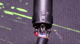
Hmmm not very good I am afraid.

What you need to do is individually apply solder to the XLR pins and then apply solder to the bare wires to "tin them"

All you then need to do is apply the heat to the two parts and push the cable into the XLR when the solder melts!
 
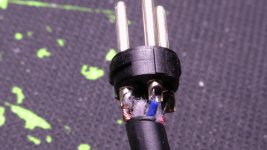
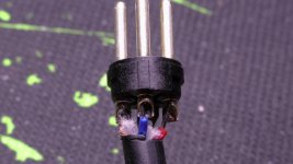
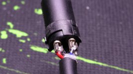
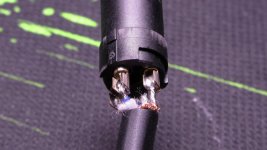
The shield looks like it's done well enough, if with maybe a little too much solder. The other two wires go into the cups at an angle; they should point straight along the axis of the pin. And it doesn't look like the solder has flowed out properly into the cups, particularly on the red wire. This could indicate not enough heat was used and could certainly lead to premature failure of the joint.

This will probably function for awhile, but if it were mine, I would take it apart and do it over.

- Greg
 
Some of the joints have too much solder (a big blob), and many of them are very "dry" (not enough solder).
There is a happy medium that you will hit with a bit more experience.

The length of your individual conductors is VERY VERY SHORT!
It is almost impossible to do a proper job of making those joints with such short wires!

I typically leave ~12mm of wire beyond the sheath, and then strip off maybe 5-6mm of the end.
And I put a good bead of solder in the cups in preparation, and tin the stripped ends of the wires.
Then I "melt" the tinned wires into the existing solder in the cups.
I've been making cables like that for ~50 years and I can count the failures on one hand.
 
I paid a guy at the place I bought the cable from to do it, I'll return it tomorrow.

Does he need to cut the entire thing and start again?

EDIT: Would audio quality be affected? Of course if it disconnects but if it holds?
 
I paid a guy at the place I bought the cable from to do it, I'll return it tomorrow.
Not a very professional job. I am rather surprised.

Does he need to cut the entire thing and start again?
No, It would probably be fine to simply "touch up" the soldering and leave everything else intact.
That assumes that there aren't any possible problems of shorting from stray shield wires coming close to the adjacent pin.

EDIT: Would audio quality be affected? Of course if it disconnects but if it holds?
It is possible that a "cold joint" could produce noise/distortion to the audio signal.
But that is not as likely as simple failure because of weak mechanical connection and flexing or pulling during use.
 
I'm with everyone else on this. When the solder sits up like that "blob" it means the joint was not hot enough for it to flow. It ought to look more like liquid sitting in the cup. The two non shields also look like they may hardly be attached, so it probably will work for awhile but you could get weird issues if it's a tentative connection where it starts acting like a crystal radio receiver. If he reheats them and gets the lead oriented correctly it sound be fine. When I had interns I would have made them redo this.
 
What do you guys think of this solder job? I'm using Neutrik connectors.
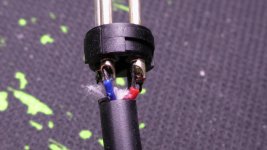
Time for a redo... Some of the lead ends look marginally minimal... Some of the points of solder leave most of the lead off the connection area...

Etc...

Balled up solder usually means the iron was not on the joint long enough to heat up the area so the solder would flow then harden. Too little solder means... too little time was taken to let the solder flow.

This may be due to the short leads, and that if one leaves the solder iron on the lead the plastic insulator starts to buckle and melt...

One thing I've noticed about modern 'soldering' is cleaning away any flux/residue. In the olden days we would use Triclor to clean up... due to all the over reacting health concerns... other cleaning agents are used these days, and from some of the work I've received... either the person didn't take the time, or the cleaning agent is not very good.
(I use to do some rework my self... but with the micro 'dot' component or ball grid arrays... forget it... but I occasionally will do cabling or other big stuff).
 
Last edited:
Back
Top