Wiring old light

jamani

Active member
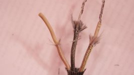
So I set out to change the plug on an old theatrical fixture from a bates stage to an edison. This being my first time doing this, I read up on it and got a good understanding of the color coding of the wires and which one is the ground, neutral and the live. Based on what I gathered from multiple sources, I was expecting blue, yellow and brown wires. On stripping the wire on the fixture, I got hit with the below image. I'm lost. Which wire is which?
IMG_1084.jpg
 
Last edited:
use a multimeter to find where each wire terminates.

if it has a switch that may give you an idea, the active and neutral will be connected at the switch and the earth should run uninterrupted to the lamp.

personally i would rewire the fitting with new a lead, take it to an electrician and have him do it, it shouldnt cost to much.

cheers
 
Last edited:
IF it was wired correctly on the Bates, the center pin would have been the ground. I would throw a meter on it and find with wire rings out to the case of the fixture. The other two lamp wires are the hot and neutral but they don't care which is which.
 
those old theatre lights were meant to hang on a lighting grid and were only subject to a gentle pan and tilt
their wiring reflects this hence the bates stage plug.

if you are using it on a stand on the ground i would recommend you rewire it with appropriate gauge wire.

cheers
 
those old theatre lights were meant to hang on a lighting grid and were only subject to a gentle pan and tilt
their wiring reflects this hence the bates stage plug.

if you are using it on a stand on the ground i would recommend you rewire it with appropriate gauge wire.

cheers

I'm curious why you seem to be saying that bates is not for a light that gets moved a lot?

Theatre lights do get handled and moved for just about every show, and often on tour where they are moved around just as much as any film light, and stage pin (as a 20a bates connector is called in the US theatre world) is a perfectly wonderful choice for this application. Also, the gauge of wire is selected based on the wattage of the lamp, not the application. If you are concerned about cable not being robust enough you should be more interested in the jacket/insulation. SO cable is going to be more robust than SJO and so on. Also, bates connectors are used in film/tv lights every day. The 60 amp and 100 amp bates connectors are ubiquitous on every set I've ever worked on.
 
i have no problem with the bates plug, i was referring to the wiring as evidenced in the supplied photo.
there are theatre lights that have been sitting on a grid for 20 years, from the picture i assumed this was one of them.
the gauge of wiring selected 20 years ago is not necessarily appropriate in todays world.

i have 30 years experience rewiring motion picture lighting and safety test and tagging but hey what would i know.

cheers
 
And I have 20 years of experience with theatre and film lighting, but there is no reason to get defensive and snarky with your "what would I know" comment. I thought this was a discussion board where we shared ideas. That is what I was doing, joining the conversation and discussing the topic. No need to take offence anytime someone questions a statement you make.
 
Let us go back to the original post and the question. One of the most pertinent pieces of info that was left out was what fixture is this? The reason I ask is because some fixtures would NOT be able to be rewired with SJ or SO cable. Take an ETC fixture, the socket is hardwired to a fiberglass coated leads that are about 40" long. You can also only get the socket with the leads as one complete kit. Now before you say, "I'll just cut and splice the leads in the fixture", you have to realize that there is NO room in either the cap of a Source 4 or a Par to do this type of thing. Furthermore, if you were to do this you would be violating the UL listing of the fixture. So back to the S4 example, there are two fiberglass coated leads that go to the lamp. It doesn't matter with one is hot or neutral. There is another THHN lead that is the ground, color is usually green but I have seen black used. This whole assembly is also covered with a fiberglass sleeve to protect from the heat. I have seen SJ cable melt when it was touching the body of many fixtures but I have yet to see a fiberglass sleeved lead melt on one.

My best advise, if you don't have a meter and don't feel comfortable ripping the fixture apart to see what wire goes to what, I would suggest taking the fixture to your local lighting, grip, or production house with a case of beer and get one of their guys to change it out for you ;) Not only will you make new friends but you may also find a great place to get lamps when you need them in the future!
 
I must admit I was confused by the idea that something rigged above has different standards to those on the ground. We have different rules here in the UK, and as mentioned above, number one on the list for rewires is current capacity, and second the type of cable. Once you've selected the appropriate current capacity, then you need to decide between heat resistant cable, such as the varieties of silicon based products or the more specialised fibre-glass insulated stuff (like the ETCs mentioned). In the UK, we tend to look at shortish lengths of silicon from the actual fixture to the connector - mainly because although silicon is great from the heat resistant point of view, it's not tough. TV lights used to have very long lantern to connector cable, and this gets hauled of scaffolding, around sharp corners and edges. Silicone isn't good at this, and splits. So if there is a switch, there could be a short length of silicone, then the switch, then tough rubber shielded cable to the connector. If there is no switch, then the short length of silicone has a connector close to the fixture - then the other plug/docket cables are TRS. Here, using anything other than the correct colours (Blue=N, Brown=Live and green/yellow = ground) would be frowned upon, and probably cause the unit to fail our appliance testing system. Practically, colours don't matter - but here, we always expect conformality - so brown is always live - and thus avoided if you see one loose! If rewiring, I;d probably go silicone to the lamp holder, and maybe even sleeve this with fibreglass!
 
Preciate the kind responses. So I decided to take the multimeter suggestions and set out to do some research on how exactly to use one for this purpose. There either isn't that much info out there on using a multimeter to find ground or I'm using the wrong search terms. It doesn't help either that I'm trying to find the ground wire on a unit that is not connected to power. The only info I was able to get is the below quote from some forum. How accurate is it? Should I follow it? Anything else I should know?

"Well.. The only way you'll find out if you can't find the schematics is if you read it out with a multimeter. Now.. you have to be very careful with this procedure if electrical power is applied, if it has internal power coming from somewhere or anything like that. If it is not plugged in anywhere then you are pretty safe, but still remember that whenever you read out a wire with possible power coming from it to put your black meter lead in a ground first. It's easy to find a good ground if you aren't familiar with electricity. If you have a multimeter set it to read ohms(which looks kind of like an upside down horseshoe symbol) I would suggest using a ground on an electrical outlet (which is the fattest hole on modern outlets and it is also underneath the two skinny slots. Be careful not to touch meter leads inside of the skinnier slots because you don't need to read out your electrical outlet, you are just looking for your ground wire. So always be sure to give your meter a ground first and foremost, and then just touch it to each wire and see if you read 0.0 ohms or 0.04 anywhere around there would be that you have found a ground. Now if you are reading 0.L. on the meter it means the ohmage is out of limits so you don't have continuity, so that means that would definitely not be your ground wire. Keep your black meter lead in the ground and move your red meter lead on to another wire until you find one that reads 0.0ish. If you get 0.0 right away I would suggest checking all the other wires just to be sure and if none of the other wires give you 0.0 then you have found your ground. Now as far as reading power out.. it's REALLY important that you have the black lead in the ground before you touch the red lead to the wire. This could cause burns or electric shock if you accidentally touch the wrong thing with your leads. And the only way you can read out power is if there is power going to the unit... so if you can't send power thru it, it might be hard to tell.... but if you can... make sure you set your meter on the right setting... Does your unit run on AC or DC electricity? If it runs on AC then move your meter to the symbol that looks like a wavy thing.. and if it runs of DC then move the dial on the meter to the symbol that has one solid line and a dashed line on top of each other. Then I must reiterate... MAKE SURE YOUR BLACK LEAD IS IN A GOOD GROUND BEFORE YOU TOUCH THE RED LEAD TO THE POSSIBLE POWER SOURCES. Also it's a good idea to do this with a buddy that knows CPR.. I don't know how electrically minded you are.... but electric shock can cause cardiac arrest and if you don't have someone there... well... I sure you understand.. if you have any doubts about your abilities... then you should probably call an electrician. But good luck and be careful."
 
Buy a $6.00 multi-meter from Harbor Freight http://www.harborfreight.com/7-function-multimeter-98025.html

Turn on the meter.
Select 2000 ohms on the dial. Depending on the meter, it may flash a number or have a static number and a partially blank readout. This means infinity resistance.
Test that the meter is working by touching the tips of the black and red leads to each other. The meter will then give a reading of 0 or just a few ohms.
Place one lead on one of the wires (it doesn't matter which lead you use). Place the other lead on the center contact inside the bulb socket.
See if you get a reading on the meter of low ohms. If you do, then this wire is the hot wire. Mark it with black tape. See picture.

Repeat the procedure for the other contact inside the bulb socket. This wire is the neutral wire. Mark it with white tape.
Repeat the procedure for the metal housing. This wire is the ground wire. Mark it with green tape.

Colored electric tape should be available at any good hardware store.

Meter_zps6f90bfa1.jpg


Now that you know which wire is which, you can wire a plug to it.

Oddly enough, the plug in the picture above is wired wrong. It has the center conductor connected to neutral.

Buy a 3 conductor plug. Take it apart and you will see that it has a gold screw and a silver screw.


Wire the black (hot) lead to the gold screw. Wire the white wire to the silver screw. Wire the green wire to the green screw.

Plug_zpsbdd527dc.jpg
 
Last edited:
Paul you have no idea how helpful this is. Thank you! Will do this over the weekend for my three lights and report once I'm done. Again, thank you.
 
Last edited:
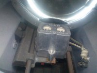
So I embarked on Paul's above process to find the respective wires on my old theatrical fixtures. I was able to find the ground partly using Paul's process and also due to the fact that it seemed pretty obvious as it was the only one screwed to the housing. Problem is I'm not sure which one is hot and which one is neutral, or whether it even matters if I am going to be rewiring it. As you can see from the image below, the contacts are designed differently from what Paul had envisioned. IS there any standard on which between the right and the left contact is the neutral and which one the hot? Does it matter?

Light.jpg
 
Agreed. The only reason one would be hot vs neutral is in an example similar to what I showed. In a household lamp that has a metal housing, it would be preferred (I don't know if it is per code) that the outside shell of the screw base be neutral as this would provide a bit more protection from the hot being in contact with the metal housing.

In the case here, there is no advantage nor difference which is which.
 
Back
Top