Where do you get four socket adapters?

seems these are plastic though. At that rate i can just screw together 3 two way adapters for about 3 bucks at home depot. Hoping to find a ceramic version.
 
just spiral bulbs from home depot. they sell them in 200w equivilants that still get me under the power load for the cable. Cheaper than ordering a larger cool light bulb.
 
Chances are you can just buy a larger bulb and use a two way socket. You also should be watching how much you put into the china ball...those things are flammable you know.
 
just spiral bulbs from home depot. they sell them in 200w equivilants that still get me under the power load for the cable. Cheaper than ordering a larger cool light bulb.

I advise you to give up your quest for a porcelain four-way socket adapter. Even if you were to find one, using four 45W CFL bulbs in it will overload the socket you screw it into. The neutral in the fixture would also overheat and melt-down, and if you tried to power several of your 4 bulb CFL Lanterns on a portable gas generator you would have power problems (not flicker) because this set up will generate severe harmonic distortion in the power supplied by the generator. Why? Because you are failing to take into account that the CFL bulbs you want to use probably have a Power Factor no better than .5 - making their actual load 90W a piece, and the load for four of them 360W. The individual sockets of the four socket adapter on ebay are only rated for 65 watts max and would eventually melt under the load of the 45W CFL bulbs because they are 46% over the sockets rated capacity. And, even if you were to find one made out of porcelain, the E26 Medium Edison Screw base socket you would screw it into would melt because, at best, it would be rated at 250W maximum and would overheat under the load of the 4 CFL bulbs as well.

Since power factor is universally overlooked in the DIY designs that I have read on this forum, and since a little knowledge can be a dangerous thing when it comes to handling electricity (case in point), I feel it necessary to repost an explanation of Power Factor and how it accounts for why Cameron McC’s idea will not work. For a more detailed explanation, I would suggest you read the article I wrote for our company newsletter on the use of portable generators in motion picture lighting, and it is not for marketing purposes, but for your own safety. In it, is a more detailed explanation of the basic electrical engineering principles behind Power Factor. The article is available on our website at http://www.screenlightandgrip.com/html/emailnewsletter_generators.html.

If we were to look up the technical specifications for the 45W DayLight 200 CFL bulbs available at Home Depot (Feit Electric Model # : ESL40TN/D/12) you would find that they have a poor Power Factor. Screw-in compact fluorescent lamps not specially made for the EU market typically have a Power Factor of only around .5, sometimes closer to .4. Some with integral electronic ballasts have "harmonic amps" so high as to have Power Factor around .35. If we assume for the sake of argument (and to keep the math simple) that they have a power factor of .5 the 45W DayLight 200 CFL bulb will in fact draw .75 Amps and not the .375 Amps one would think using Ohm’s Law (W=VxA.) The difference between the actual current drawn by the bulb (.75A) and the .375A Cameron McC assumes using Ohm’s Law (W=VxA), is the difference between what is called “Apparent Power” and “True Power.”

If, in this case, you were to measure the current (using a Amp Meter) and voltage (using a Volt Meter) traveling through the cable supplying the CFL bulb and multiply them according to Ohm’s Law (VxA= W) you would get the “apparent power” of the bulb (120V x .75A = 90W). But, if you were to instead, use a wattmeter to measure the actual amount of energy being converted into real work (light) by the ballast of the CFL bulb you would get the “true power” of the bulb which in this case is specified by the manufacturer as 45W. The ratio of “true power” to “apparent power” is called the “Power Factor” of the bulb.

A favorite analogy electricians like to use to explain Power Factor is that if Apparent Power is a glass of beer, Power Factor is the foam that prevents you from filling the glass all the way up with beer. When lights with a low Power Factor are used, the distribution system must be sized to supply the Apparent Power (beer plus foam), even though only the True Power (beer) counts. What accounts for this discrepancy between Apparent Power and True Power?

Incandescent_Bulb.jpg

Wiring schematic of an incandescent bulb ​

To understand the Power Factor of a CFL bulb, and its’ effect on the power supply, it is helpful to compare it to an incandescent bulb. As can be seen in the circuit diagram above, by comparison an incandescent light is a simple resistive load. The high resistance of its tungsten filament creates heat until the filament glows - creating light. As we see in the oscilloscope shot below, of a 25W incandescent bulb operating on grid power, the current is always proportional to the voltage (current is represented on the scope as the voltage drop on a 1 Ohm resistor.)

Incan_Waveform.jpeg

Current and Voltage Waveform of a ACEC 25W Incandescent bulb ​

If the applied voltage is sinusoidal, the current generated is also sinusoidal. That is, the current increases proportionately as the voltage increases and decreases proportionately as the voltage decreases. Since the peak of the voltage corresponds to the peak in current, the voltage and current are also in phase and so have a unity power factor (Power Factor of 1.)

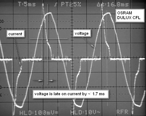
The voltage and current waveforms below of a CFL bulb operating on grid power is very different from that of the incandescent light above. The most noticeable difference is that the current, generated by the CFL bulb, no longer proportionately follows the nice smooth sinusoidal voltage waveform supplied to it by the power grid. Rather, it has been distorted by electrical components in the ballast of the CFL bulb so that it instead consists of sharp spikes in power that quickly drop off over a short duration. A second distinguishing characteristic is that the peak of the voltage no longer corresponds to the peak in current. The current now “leads” the voltage by 1.7 milli-seconds. The voltage and current are no longer in phase as in the case of an incandescent bulb, but instead exhibits what we call a Leading Power Factor.

CFL_Waveform.jpg

Current and Voltage Waveform of a Brelight 25W CFL Bulb​

The distorted current waveform and Leading Power Factor exhibited here is caused by components in the electronic ballast which use only portions of the voltage waveform, draw current in quick bursts, and then return the unused portions as harmonic currents that stack on top of one another, creating harmonic distortion that pulls the voltage and current out of phase. This creates an opposition to the flow of current that is called Capacitive Reactance. Where Capacitive Reactance leads to an inefficient use of power (lots of foam), and the harmonic currents generated can have severe adverse effects on other equipment operating on the same power, it is worth exploring the cause of Capacitive Reactance and the source of the harmonic currents in more detail.

schematic_CFL_ballast.jpg

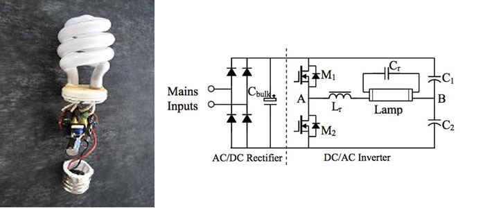
Typical schematic of CFL electronic ballast: L-to-R consists of half-bridge rectifier, conditioning capacitor, DC/AC Inverter​

The electronic ballasts of self ballasted CFLs, are very similar in design to the high frequency ballasts used in fluorescent movie lights in general (Kino Flo, Lowell, etc.) All electronic fluorescent ballasts are essentially AC-to-AC power converters in that they convert line-frequency power from the utility company (60Hz) to a high-frequency AC power (20’000-50’000 Hz) to excite the gases in the fluorescent lamp so that they glow continuously. The diagram above illustrates the typical components that make up the high-frequency electronic ballasts found in most all high frequency fluorescent movie lights and CFL bulbs.

SMPS_Rectified_Power_Flo.jpg

Step 1: Rectifier Bridge converts AC power to rectified sine wave. Step 2: rectified sine wave is flattened to DC by conditioning capacitor. ​

They consist, first, of a diode-capacitor section that converts the AC input power to DC power, and then an inverter section that converts the DC power back to a high frequency AC power that ignites the lamp gases. The diode-capacitor section converts the AC power to DC power by first feeding the AC input current through a bridge rectifier, which inverts the negative half of the AC sine wave and makes it positive. The rectified current then passes into a conditioning capacitor which removes the 60 Hz rise and fall and flattens out the voltage - making it essentially DC. The DC is then fed from the conditioning capacitor to the inverter section which typically consists of a pair of MOSFETs (metal–oxide–semiconductor field-effect transistors) which generate the high frequency (20-50kHZ) AC waveform. Where, the harmonic currents produced by electronic fluorescent ballasts are primarily generated by the diode-capacitor section of the ballast, lets look at how this circuit works in more detail.

Where I am just about out of space, I will pick up with how the diode-capacitor section of fluorescent and HMI electronic ballast generates harmonics in my next post.

Guy Holt, Gaffer, ScreenLight & Grip, Boston
 
Where I am just about out of space, I will pick up with how the diode-capacitor section of fluorescent and HMI electronic ballast generates harmonics in my next post.

Where, the harmonic currents produced by electronic fluorescent ballasts are primarily generated by the diode-capacitor section of the ballast, lets look at how this circuit works in more detail.

As shown in the illustration below, the diode-capacitor circuit only draws current during the peaks of the supply voltage waveform and charges the conditioning capacitor to the peak of the line voltage. Since the conditioning capacitor can only charge when input voltage is greater than its stored voltage, the capacitor charges for only a very brief period of the overall cycle time. After 90 degrees, the half cycle from the bridge drops below the capacitor voltage; which back biases the bridge, inhibiting further current flow into the capacitor. Since, during this very brief charging period, the capacitor must be fully charged, large pulses of current are drawn for short durations. Consequently, electronic ballasts draw current in high amplitude short pulses. The remaining unused current feeds back into the power stream as harmonic currents.

Working_of_CFLs.jpg

Yellow Trace: Rectifier Bridge converts AC power to rectified sine wave. Blue Trace: Stored Capacitor Voltage. Red Trace: Current drawn by capacitors once input voltage is greater than voltage stored in the capacitor (Blue trace.) ​

These simple diode-capacitor circuits are used in CFL bulbs and in many fluorescent movie lights because they are compact and inexpensive. However, they have a number of drawbacks. For instance, notice how big the input current spike (red trace above) of the diode-capacitor circuit is. Without power factor correction, the in-put bridge rectifier requires a large conditioning capacitor at its output. This capacitor results in line current pulses (as seen in our oscilloscope shot in the previous post) that are very high in amplitude. All the circuitry in the ballast as well as the supply chain (the generator, distribution wiring, circuit breakers, etc) must be sized to carry this high peak current (the foam in our analogy). Also notice that the line current pulses are narrow, with fast rise and fall times. Since the diode-capacitor circuit uses only the peaks of the voltage waveform, they generate high harmonic content as the unused portions of the voltage waveform are returned as harmonic currents (see graph below.)

CFL_Harmonic_Distro.jpg

Distribution of Harmonic Currents generated by CFL bulb​

These harmonic currents stack on top of one another creating harmonic distortion that creates an opposition to the flow of current; and, as we saw in the oscilloscope shot in the previous post, pulls the voltage and current out of phase. When the power is supplied by a conventional generator these harmonic currents can also lead to severe distortion of the voltage waveform in the power distribution system (see below for more details.) Finally, the fast rise time of these harmonic currents can cause Radio Frequency Interference (RFI) problems. For this reason, on their website Lowell warns about their compact fluorescent (CFL) fixture, the Lowel Ego, that: “The lamps may cause interference with radios, cordless phones, televisions, and remote controls. If interference occurs, move this product away from the device or move to a different outlet” (http://www.lowel.com/ego/lamp_info.html.) While self ballasted CFLs generate the most severe harmonics, all electronic ballasts (both fluorescent and HMI) generate harmonic currents (see table below.)

Table_THD_Flo_Ballasts.jpg

When you plug an electronic ballast (fluorescent or HMI) into a wall outlet, you need not be concerned about current harmonic distortion producing voltage distortion. The impedance of the electrical path from the power plant to the outlet is so low, the distortion of the original applied power waveform so small (less than 3%), and the power plant generating capacity so large by comparison to the load, that harmonic currents fed back to it will not effect the voltage at the load bus (electrical outlet.) However, it is an alltogether different situation when plugging electronic ballasts (fluorescent or HMI) into a portable generator.

For a rather amusing demonstration of the adverse effects that poor Power Factor light sources can have on generators check out this You-Tube video, “Compact Fluorescent verses the generator,” at http://www.youtube.com/watch?v=LeCqreRMzKM. In this test, lighting designer Kevin Shaw, first operates a 575W ETC Source Four Leko with Quartz Halogen bulb on a 650W two stroke gas generator without problem. However, when he tries to operate an equivalent wattage of CFLs (30-18W bulbs) the generator goes berserk. Only after turning off half the CFL Bulbs does the generator operate normally with the remaining a 270W load. What accounts for the erratic behavior of the generator in this video? It is a combination of the poor Power Factor of the CFL bulbs and the harmonic currents they generate.

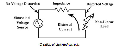
In this case, the impedance of the power generating system (generator and distribution cable) is sufficient enough that a harmonic currents generated by the CFL bulbs induce a voltage at the same frequencies. For example, a 5th harmonic current produces a 5th harmonic voltage, a 7th harmonic current produces a 7th harmonic voltage, etc. Since, as we saw above, a distorted current waveform is made up of the fundamental plus one or more harmonic currents, each of these currents flowing through an impedance will, result in voltage harmonics appearing at the load bus, a voltage drop, and distortion of the voltage waveform.

Creation_of_Harmonics_Flow.jpeg

Each harmonic current in the electrical distribution system will cause a voltage at the same harmonic to exist when the harmonic current flows into an impedance. ​

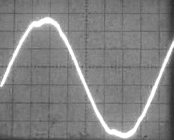
Since electronic ballasts (Fluorescent as well as HMI) consume current only at the peak of the voltage waveform (to charge the smoothing capacitor/s), voltage drop due to system impedance occurs only at the peak of the voltage waveform. In this fashion, the pulsed current consumed by electronic ballasts produces voltage distortion in the form of flat-topping of the voltage waveform.

CFL_FlatTop_Waveform.jpg

The pulsed current consumed by electronic ballasts produce voltage distortion in the form of flat-topping.​

For example, the power waveform above (from my article) is what results from the operation of a 2500W load consisting of non-Power Factor Corrected electronic Kino & HMI ballasts on a conventional portable generator (a Honda EX5500 with a Barber Coleman Governor.) It is also a good indication of what would likely result from operating Cameron McC’s CFL lanterns along with several small HMIs on a conventional putt-putt generator. Since the voltage waveform distortion exhibited here can adversely effect other equipment operating on the same power, the generation of harmonic currents by electronic HMI & Fluorescent ballasts should be eliminated whenever possible.

Where I am just about out of space, I will pick up with how Cameron McC could mitigate the problems caused by harmonic currents and make his CFL Lantern work in my next post.

Guy Holt, Gaffer, ScreenLight & Grip, Boston
 
Where I am just about out of space, I will pick up with how Cameron McC could mitigate the problems caused by harmonic currents and make his CFL Lantern work in my next post.

Since the voltage waveform distortion exhibited in my post above can adversely effect other equipment operating on the same power, the generation of harmonic currents by electronic HMI & Fluorescent ballasts should be eliminated whenever possible. If not, they can build to a point where they will have a disastrous effect upon other equipment. As more and more electronic components, like lap top computers, hard drives, and HD monitors, which are themselves sources of harmonic distortion (but of a lower amplitude than solid state lighting ballasts) are integrated into the typical location production package, harmonic currents begin to combine with unpredictable consequences. In fact, a viscous cycle can get started. The more harmonic orders that are generated, the more distorted the power supplied by the generator becomes. The more distorted the power waveform becomes, the more harmonic currents are thrown back into the electrical distribution system, which in turn, creates additional voltage distortion. In this fashion, something akin to a feedback loop can get started. Very often, the operation of production equipment may seem normal, but under a certain combination of conditions, the impact of harmonics is enhanced with unpredictable results.

makeup_squarewave_alt.gif

Sprectrum analysis of the high frequency Harmonic Currents that induce a flat-topped voltage waveform at the load bus.​

For instance, the severe voltage waveform distortion exhibited above can cause overheating and failing equipment, efficiency losses, circuit breaker trips, and instability of the generator's voltage and frequency. In addition to creating the radio frequency interference (RFI) mentioned on the Lowell Light website, harmonic noise of this magnitude can also cause component level damage to HD digital cinema production equipment and create ground loops. Harmonics can also cause excessive current on the distribution system neutral (see below.) And, since the neutral conductor of a distribution system is not fused, it can cause the neutral to overheat and possibly melt down.

High_Nuetral_Return_CFL.jpg

Substituting incandescent lamps with the equivalent wattage of CFLs in a small single phase distribution system substantially increases the current on the system neutral.​

For this reason, on their website Kino Flo cautions users of their older style fixtures, that the ballasts “will draw double the current on the neutral from what is being drawn on the two hot legs. On large installations it may be necessary to double your neutral run so as not to exceed your cable capacity.”(FAQ “Why is the neutral drawing more than the hot leg”.) For a detailed explanation for why harmonic currents cause unusually high neutral returns see my article on the use of portable generators in motion picture production available on our website at http://www.screenlightandgrip.com/html/emailnewsletter_generators.html.

The first step in mitigating the problems caused by harmonic currents is to eliminate the currents. Where customarily the largest source of harmonic currents in a typical lighting package are HMI and Fluorescent lights with electronic ballasts, using only ballasts with Power Factor Correction (PFC) circuitry will go a long way in reducing the number of harmonic currents in the power stream. By simply eliminating the generation of harmonic currents, a PFC circuit realigns voltage and current and induces a smoother power waveform at the distribution bus. As a result, the ballast uses power more efficiently with minimized return current and line noise and also reduces heat, thereby increasing their reliability (see my article for a more detailed explanation on how Power Factor Correction works.)

Effect_of_PFC_in_Flos.jpg

The second step in mitigating the problems caused by harmonic currents is to use inverter generators. The combination of the improved power factor of the ballasts and the nearly pure power waveform of inverter generators makes it possible to reliably power larger lights, or more smaller lights, than has been possible before on a small portable gas generator. For example, the power waveform below, is the same 2500W load as above but with power factor correction operating on our modified Honda EU6500is Inverter Generator. As you can see, the difference between the resulting waveforms is startling. Even though the load is the same, the fact that it is Power Factor Corrected, and the power is being generated by an inverter generator, results in virtually no power waveform distortion. For this reason, sensitive electronic production equipment will operate reliably and without damage on the same power. And, the generator is capable of operating larger, or more smaller, lights than has ever been possible before on a portable gas generator.

waveform_Inv_PFC_kino.jpg

The nearly pure voltage waveform of Power Factor Corrected ballasts operating on an inverter generator. Note: No Flat Topping ​

The extremely low line noise exhibited in the inverter generator power waveform above creates a new math when it comes to calculating the lighting load you can put on a portable generator. Where before you could not operate more than a couple 1200W HMIs with non-PFC ballasts on a conventional generator because of the consequent harmonic distortion, now you can load an inverter generator to capacity. According to this new math, when you add up the incremental savings in power to be gained by using only PFC HMI ballasts, add to it energy efficient sources like the Kino Flo ParaBeam fixtures (which are also PFC), and combine it with the pure waveform of inverter generators, you can run more HMI and Flo lights on a portable gas generator than has been possible before. For example, the 7500W capacity of our modified Honda EU6500is Inverter Generator can power a lighting package that consists of a PFC 2.5kw HMI Par, PFC 1200, & 800 HMI Pars, a couple of Kino Flo ParaBeam 400s, a couple of ParaBeam 200s, and a Flat Head 80. Given the light sensitivity of HD cameras, this is pretty much all the light you will need for a low budget HDV production. Use this link - http://www.screenlightandgrip.com/html/emailnewsletter_generators.html - for more information about the benefits of low line noise.

There are CFLs that have a “resonance tuning" capacitor circuit added to provide Power Factor Correction. Unfortunately, for Cameron McC these are available only in Europe because the European testing agency TUV mandates it. Power Factor Corrected CFL lamps are generally not available here in the U.S. because the “U.L. Approval" stamp we are familiar with here does not require Power Factor Correction. Cameron McC’s best bet is to make up his own four socket CFL fixture with a beefed up neutral so that it doesn’t overheat and use an inverter generator when he needs to power his CFL lantern lights on locations without grid power. If he takes these precautions he should have no problem.

If a reader of this post still doesn’t entirely understand power factor, I would encourage them to read the article I wrote for our company newsletter on the use of portable generators in motion picture lighting before attempting to build their own lights. In it, is a more detailed explanation of the basic electrical engineering principles behind harmonic distortion and it’s adverse effects. The article is available on our website at http://www.screenlightandgrip.com/html/emailnewsletter_generators.html.

Guy Holt, Gaffer, ScreenLight & Grip, Boston
 
Very interesting. FYI the sockets are made of a poly carbonate, same as my Glock 40 calibre and the rating on the fixture is rated at 250 watts.
Gary
 
Guy,

It seems to be your conclusion that the entire lightbulb industry is committing a massive fraud on consumers?

If a bulb is labeled "26 watts" then it should draw no more than 26 watts. Is this true or false? Have you measured results across a wide sampling of CFL bulbs?
 
Guy,

It seems to be your conclusion that the entire lightbulb industry is committing a massive fraud on consumers?

If a bulb is labeled "26 watts" then it should draw no more than 26 watts. Is this true or false? Have you measured results across a wide sampling of CFL bulbs?

Perhaps "fraud" isn't the proper term for people who don't understand AC power factors, etc. I would reserve the term "fraud" for the Government who wants us to replace all incandescent globes with CFL. Now THERE is a group of people who know nothing about what they are doing.
 
I have been wondering that. Seeing whats actually inside a CFL makes me wonder how "green" they really are. Seems like a lotta waste for a little savings in power consumption.
 
It seems to be your conclusion that the entire lightbulb industry is committing a massive fraud on consumers?

I am not so paranoid to think that there is a massive fraud being perpetrated on consumers, but there are those who do. For instance check out this article on Pure Engergy Source’s Peswiki website titled “Are U.S. CFL's Designed to Make Us Pay More on Our Power Bills?” by Steve Windisch, available online at: http://peswiki.com/index.php/Article:Are_U.S._CFL's_Designed_to_Make_Us_Pay_More_on_Our_Power_Bills?.

The synopsis of the article reads: “CFLs have been touted to save energy, and they do certainly save significant amounts of electricity. But there are some interesting and largely unknown facts about these devices. It would appear that those sold within the United States and other countries may be specifically designed to allow the utility corporations to bill us nearly double what we should be paying for their use.”

If you are a conspiracy nut, you will love this article.

Guy Holt, Gaffer, ScreenLight & Grip , Boston
 
If a bulb is labeled "26 watts" then it should draw no more than 26 watts. Is this true or false?

False! What the bulb manufacturer is advertising is the "True Power" of the bulb or how much light (work) it generates. That is quite different from the "Apparent Power" or the load it puts on the electrical distribution system. The difference between the two is Power Factor.

Since Power Factor Correction (PFC) is not mandated in this country, as it is in Europe for any electrical device that draws more than 75W, we are pretty much ignorant of Power Factor and effects that poor Power Factor can have on a distribution system. However, any film technician familiar with large HMI heads will be quite familiar with Power Factor and Power Factor Correction (PFC.) That is because after a false start back in the 90s, all major manufacturers now include PFC circuitry in HMI ballasts in the 6-18kw range. They do so by necessity. The early line of Lightmaker electronic ballasts were nick named by film electricians “Troublemaker” ballasts because they proved that PFC circuitry was absolutely necessary in large ballasts to reduce heat and returns on the neutral, and to increase ballast reliability (beware, some are still kicking around ebay). But, because of the added cost, weight, and complexity of PFC circuitry, ballast manufacturers in the US still only offer PFC circuitry as an option in medium-sized 2.5-4kw ballasts. And, until very recently manufacturers did not offer PFC circuitry in HMI ballasts smaller than 2.5kw in the US (in the EU PFC circuitry in mandatory in all HMI ballasts sold.)

Part of the problem was that PFC circuitry did not offer a huge advantage when plugging into house power. A typical 1200W Power Factor Corrected electronic HMI ballast will draw 11 Amps at 120 Volts verses the 19 Amp draw of a non-PFC electronic ballast. While not a huge advantage when plugging into house power, the added efficiency of a PFC 1200 ballast can make a huge difference when powering a lighting package off of a portable generator. For example, when you consider that a Kino Flo Parabeam 400 draws only 2 amps, the 8 Amp difference between using a PFC 1200W electronic ballast and standard non-PFC 1200W electronic ballast, can mean the difference between running four additional Parabeam 400s on a portable generator or not – I think you would have to agree that is a major boost in production capability and pertinent to any one using a portable generator as their principle source of set power.

But that is not the only benefit to using PFC electronic ballasts. The substantial reduction in line noise that results from using power factor corrected ballasts on the nearly pure power waveform of an inverter generator creates a new math when it comes to calculating the load you can put on a generator. In the past we had to de-rate portable gas generators because of the inherent short comings of conventional generators with AVR and Frequency governing systems when dealing with non-PFC electronic ballasts. The harmonic distortion created by non-PFC ballasts reacting poorly with the distorted power waveform of conventional AVR generators limited the number of HMIs you could power on a portable generator to 75% of their rated capacity (4200Watts on a 6500W Generator). But now, where inverter generators have virtually no inherent harmonic distortion or sub-transient impedance and power factor correction (PFC) is available in small HMI ballasts, this conventional wisdom regarding portable gas generators no longer holds true. Where before you could not operate more than a couple 1200W HMIs with non-PFC ballasts on a conventional generator because of the consequent harmonic distortion, now according to the new math of low line noise, you can load an inverter generator to capacity. And if the generator is one of our modified Honda EU6500is inverter generators, you will be able to run a continuous load of up to 7500W as long as your HMI and Kino ballasts are Power Factor Corrected.

Except for one notable exception, when manufacturers do offer PFC circuitry in smaller ballasts it is at a premium, adding as much as a $1000 to the cost of a 1200W ballast for instance. The new ballast manufacturer Power-2-Light, on the other hand, is including PFC circuitry in their ballasts at the same price point as other manufacturer’s non-PFC ballasts. But where Power-2- Light is still very new to the market, it is still the case that almost every 575 - 1200 W ballast that you will find in a rental house in North America will be a non-PFC electronic ballast. Don’t blame the rental houses, until recently they never were offered the choice.

Common questions I hear are why haven’t we needed Power Factor Correction in HMIs until now? Why do PFC circuits cost so much? And, how do they work? Since, this is getting off the topic of this thread I have started a new thread ( What is Power Factor Correction in HMIs) to answer these questions.

Guy Holt, Gaffer, ScreenLight & Grip , Boston
 
Back
Top